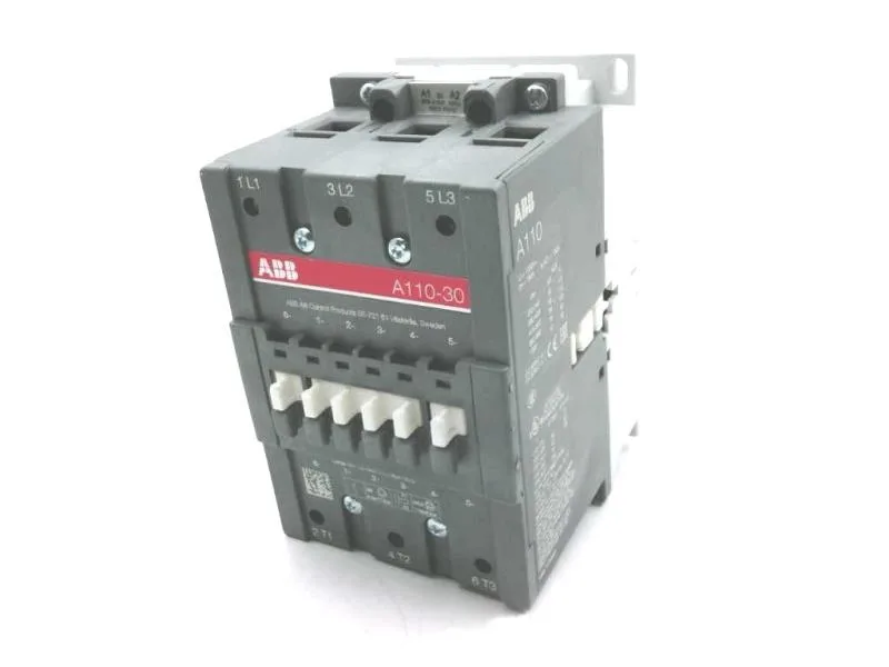
The A110-30-11-51: Rated 110 A continuous — this is the thermal current (Ith), not the motor locked-rotor current; the contactor must carry the full-load amps of the driven load without exceeding its temperature rise limit. For a motor branch circuit, the contactor is typically selected at 1.15× the motor FLA per NEC 430.83, so a 110 A contactor covers motors up to about 95 A FLA. The 480 V AC coil means the control circuit must deliver 480 V at the coil terminals during pick-up and hold. On a 400 V nominal system the coil pulls in but may drop out at 85 % of rated voltage (408 V) — verify the control transformer tap and the voltage sag during motor starting. Three poles, non-reversing, across-the-line switching — this is the standard three-phase motor contactor layout. The 1 NO + 1 NC auxiliary contacts are built into the base unit: the NO contact signals the PLC that the contactor has closed; the NC contact blocks the backup starter from closing.
End-of-life hot — sourcing window is closing
No stock-holding claim; each order is confirmed against the available surplus or remaining factory inventory.
Peer comparison — not a drop-in for the AF25 frame
The closest listed peer is the ABB 1SBL136061R2110 (AF25, 25 A, 3-pole, DIN rail, screw terminals). That is a different frame size — the A110-30-11-51 is a 110 A frame with a larger physical footprint and different mounting hole pattern. The AF25 will not carry the same load or fit the same panel cutout; a board spin or panel re-layout is required if switching to the smaller frame.