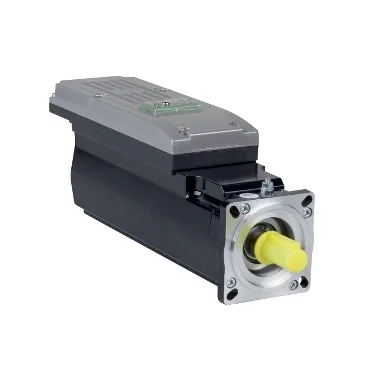
Where this motor drops in the PacDrive 3 stack
The ILM0703P21A0000 is a PacDrive 3 ILM-series servo motor integrated drive — a 70 mm flange-frame brushless servo sized for the mid-power motion axis where a PacDrive 3 controller is already driving the bus. It runs naturally cooled with an IP65 seal on the body, so the motor sits comfortably next to the gearbox on a packaging or assembly machine without needing a fan slot in the cabinet. For a commissioning engineer, the headline decision is whether the 1.15 N·m nominal / 8.7 N·m peak envelope covers the axis — the numbers below tell you exactly that.
Torque, power and current envelope
Continuous nominal torque is 1.15 N·m at 6000 rpm, with 720 W of nominal mechanical output power — that is the working point the drive loop will hold most of the cycle. Peak stall torque reaches 8.7 N·m and continuous stall torque 2.2 N·m, which sets the ceiling for short acceleration bursts on a conveyor, indexing table or small-format pick-and-place axis. Line rated current sits at 1.5 A nominal with a 12 A Irms peak, and the torque constant of 0.76 N·m/A at 120 °C is the figure the drive uses to convert current demand into shaft torque — matching this to the PacDrive 3 sizing tool is what keeps the motor out of the I²t trip zone. Continuous stall current is 3 A, so a holding brake application must be sized from that figure rather than the nominal — the motor will sit at 3 A any time it stalls against a load.
Electrical constants the drive loop needs at first start
Back-EMF constant is 49 V/krpm at 20 °C, stator resistance 2.7 Ω phase-to-phase at 20 °C dropping to 1.88 Ω phase-to-neutral at 120 °C, and stator inductance 13 mH phase-to-phase at 20 °C / 6.5 mH phase-to-neutral at 120 °C — these are the auto-tune inputs the PacDrive 3 expects to read back from the motor nameplate or Hiperface memory. Feedback is absolute single-turn SinCos Hiperface with 128 periods of resolution, which gives absolute position from power-up without a homing move — useful on a midnight startup where the controller boots and the line must know where the axis is before the first move command. Six poles and three motor stacks define the electrical architecture behind those constants — the drive counts pulses against the pole pair count to close the commutation loop.
Mechanical fit, shaft and bearing loads
The motor mounts on an international-standard flange with a 70 mm flange face, a 60 mm centring collar taken 2.5 mm deep, and four 5.5 mm mounting holes — it drops onto the same footprint pattern as other ILM-frame PacDrive 3 motors, which keeps the mechanical design simple when an axis is resized. The shaft is 14 mm diameter, 30 mm long and untapped, with no second shaft end and no holding brake — coupling choice is a clamp or compression hub rather than a tapped retainer, and an external brake must be specified separately if the axis needs a fail-safe stop. Maximum radial load Fr runs from 730 N at 1000 rpm down to 400 N at 6000 rpm, and maximum axial load Fa is constrained to 0.2 × Fr — at 6000 rpm with a belt or pinion on the shaft end, the bearing load budget is the figure that governs the coupling geometry, not the torque rating.
Sourcing reality for this exact order code
Independent distribution covers this code against an RFQ: pricing and availability are confirmed at quote time against the requested quantity, with no live stock figure published on this listing.