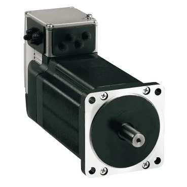
Schneider Electric ILS1B851PB1F0 — Servo Drives

Schneider Electric ILS1B851PB1F0 Servo Drive, 6 N·m, 24/36 V

MPNILS1B851PB1F0
Active

Schneider Electric, Lexium integrated drive series, ILS stepper drive, ILS1B851PB1F0, 85 mm flange, 6 N·m holding brake, 24/36 VDC.

Sourced new & surplus through independent channelsAuthenticity-screened · ESD-safe packingListing updated Aug 2026

Specifications

ILS1B851PB1F0 — Identification
ParameterValue
Device short nameILS
Product rangeLexium integrated drive
Product typeMotion integrated drive
ILS1B851PB1F0 — Electrical
ParameterValue
Rated supply voltage36 V 24 V
Supply voltage limits18...40 V
ILS1B851PB1F0 — Motor & Torque
ParameterValue
Continuous stall torque17.7 lbf.in (2 N.m)
Peak stall torque17.7 lbf.in (2 N.m)
Nominal speed200 rpm 24 V 400 rpm 36 V
Nominal torque17.7 lbf.in (2 N.m)
Rotor inertia1.3 kg.cm²
Holding brakeWith
Number of motor poles6
Number of motor stacks1
Maximum radial force (Fr)100 N
ILS1B851PB1F0 — Feedback
ParameterValue
Feedback typeIndex pulse
Speed feedback resolution20000 points/turn
ILS1B851PB1F0 — Mechanical
ParameterValue
Shaft end typeUntapped
Motor flange size3.3 in (85 mm)
Second shaft endWithout second shaft end
Number of mounting holes4
Mounting hole circle diameter3.9 in (99 mm)
Length7.4 in (187.3 mm)
Mounting hole diameter0.3 in (6.5 mm)
Centring collar diameter2.4 in (60 mm)
Shaft diameter0.5 in (12 mm)
Shaft length1.2 in (30 mm)
Centring collar depth0.08 in (2 mm)
ILS1B851PB1F0 — Environmental
ParameterValue
IP ratingIP41 shaft bushing: conforming to EN/IEC 60034-5 IP54 total except shaft bushing: conforming to EN/IEC 60034-5
Cooling methodNatural convection

Product details

What the ILS1B851PB1F0 actually drives

The ILS1B851PB1F0 sits inside Schneider's Lexium integrated drive (ILS) family, combining a 3-phase stepper motor with on-board drive electronics so a single module carries both the power stage and the motion controller. It is wired through a printed circuit board connector and uses four signals configurable as inputs or outputs for end-of-travel limits, enable, fault, or pulse direction depending on the host controller. Power enters as a DC bus on a single-phase architecture; the part carries CE marking and is designed to EN/IEC 61800-3 (second environment) plus EN/IEC 50178, which is the industrial drive EMC and insulation book. Practically, that means the module is meant to live inside a machine cabinet, not on the open factory floor, and it should be grounded through the PCB connector shield path the way the integration manual specifies.

Torque, speed, and the holding brake

The integrated holding brake pulls in with 22 W and releases in 40 ms; with a 6 N·m holding figure the brake is sized for the same shaft load the motor produces, so axis sizing is a single envelope rather than a motor-plus-brake pair. Index-pulse feedback gives homing accuracy to ±6 arc minutes, which is the figure that matters when this drive is paired against a reference mark in a registration cut.

Safety functions and EMC envelope

Current consumption is capped at 5000 mA maximum and cooling is by natural convection only, so the cabinet layout must keep the surrounding free-air space the integration manual calls out. Mechanical environment is rated to EN/IEC 60068-2-6 vibration (20 m/s² across 10–500 Hz for 10 cycles) and 60068-2-29 shock (150 m/s² for 1000 shocks), with 15–85% non-condensing humidity and 1000 m altitude without derating — a typical indoor panel envelope, not a washdown or outdoor deployment.

Mechanical fit into the machine frame

The 85 mm flange is the standard NEMA 23-class footprint for this class of integrated drive, with a 7.4 in (187.3 mm) body length, 12 mm shaft diameter, 30 mm shaft length, and untapped shaft end. Centring collar depth is 0.08 in (2 mm) — the small clearance that drives whether a customer can reuse an existing mounting plate or needs a new adapter. There is no gearbox, no second shaft end, and no integrated gear option on this code. Communications ride on a multi-drop RS-485-style link supporting 9.6, 19.2, 45.45, 93.75, 187.5, 500, 1500, 3000, 6000, and 12000 kbauds; that ladder is the Lexium ILS default, and the right rate is whichever matches the host motion controller's bus cycle — not the highest number on the list.

Sourcing posture for the BOM line

CE compliance and the EN/IEC 61800-3 (second environment) conformance are the approvals a European machine builder will ask for at the declaration of conformity step.

Frequently asked questions

What is the ILS1B851PB1F0's listed phase and DC bus voltage?

The ILS1B851PB1F0 is single-phase input on a DC network, and its nominal speed envelope is 200 rpm at 24 V or 400 rpm at 36 V — the bus voltage is what sets the application's usable speed.

Who supplies the ILS1B851PB1F0 and how is it priced for volume?

Independent distribution handles the ILS1B851PB1F0 against an RFQ, with current pricing and lead time confirmed at quote time. Volume breaks and authorized traceability are worked out per BOM quantity on the quote, not on a generic shelf price.

What compliance documentation does Schneider Electric provide for the ILS1B851PB1F0?

The ILS1B851PB1F0 is CE marked and conforms to EN/IEC 61800-3 (second environment), EN/IEC 50178, EN 50347, and IEC 60072-1, plus IEC 61800-3 Ed 2 — the EMC, insulation, and motor-mechanical standards that go into a Schneider Declaration of Conformity for this drive family.

What is the ILS1B851PB1F0's mechanical envelope — flange size and body length?

The ILS1B851PB1F0 mounts on an 85 mm flange with a 7.4 in (187.3 mm) body length, a 12 mm untapped shaft at 30 mm long, and a 2 mm centring collar — standard NEMA 23-class footprint for this Lexium integrated drive family.

MPN
ILS1B851PB1F0