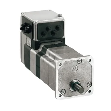
A brushless DC head with a 54:1 worm stack under it
Schneider Electric's ILE2E661PB1A6 is an ILE-class Lexium integrated drive: a brushless DC motor with a 54:1 (1715:32) worm gear, 3 stages, in a 66 mm flange format, 9.02 in (229 mm) long. The device short name ILE and the Lexium integrated drive range identify it as the all-in-one head — motor, gearbox, feedback and comms in one body — not a separate servo amplifier driving a stand-alone motor. The drive runs on a single-phase DC bus, 24 V or 48 V nominal, with supply limits of 18 to 55.2 V. Nominal speed is 75 rpm on either rail and nominal torque is 53.1 lbf.in (6 N.m) on both 24 V and 48 V, which means the gearbox — not the motor windings — sets the mechanical output across the supported supply window. Peak stall torque reaches 123.29 lbf.in (13.93 N.m), so headroom is roughly 2.3× nominal for transient indexing moves before the integrated protection flags a fault.
Where the worm reduction earns its place
Output shaft is a hole-type (blind) shaft end without a second shaft, flange-mounted, with no holding brake. For applications that need a failsafe brake (vertical axes, safety-rated stops) the absence of an integral brake is a real constraint — the holding has to come from the worm's self-locking plus the controller's safe torque off.
Protection, feedback and the comms side
Integrated protection covers overload of output voltage, short circuit of the output voltage, and safe torque off — the STO function is the safety circuit interface and the lever for compliance to the EN/IEC 61800-3 family of standards that the unit is built to. Feedback is a BLDC encoder on the motor shaft, and four signals are exposed as configurable inputs or outputs, which is enough for end-of-travel limits, a home sensor and a ready output without an external I/O block. Network comms run at 100 Mbits, wired through a printed circuit board connector — not a cordset — so the cable management is the integrator's responsibility and the connector pinout is what locks the BOM. Current consumption is 7000 mA peak and 5500 mA maximum continuous; on a 24 V rail that is roughly 168 W peak at the bus, against 45 W nominal output at 24 V, so the supply sizing and the cabinet thermal budget both need to absorb the inrush. Cooling is natural convection only — no fan, no finned heatsink duty.
Mechanical envelope and compliance footprint
Shock resistance is 150 m/s² for 1000 shocks and vibration resistance 20 m/s² from 10 to 500 Hz over 10 cycles, both per EN/IEC 60068-2 test methods — figures that put the drive inside cabinet-mounted machinery and most conveyor-side frames, not on a high-shock press directly. Operating altitude is up to 3280.84 ft (1000 m) without derating, humidity 15 to 85 percent non-condensing, and bearing service life is 6000 h — a figure that frames this as an MRO-spared component in continuously cycled lines rather than a 50,000-hour plant backbone. The unit carries CE marking and is built to EN 50347, EN/IEC 61800-3, EN/IEC 50178 and IEC 60072-1.