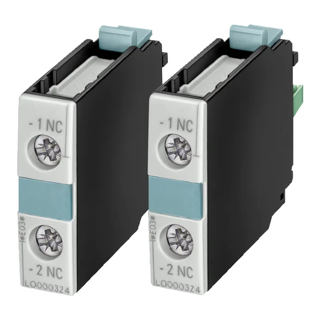
It snaps onto the contactor relay or power contactor and adds two instantaneous N/O contacts for status feedback, interlocking, or control logic. The screw-type terminals accept 2x (0.5...1.5 mm²) solid or stranded, or 2x (0.75...2.5 mm²) — the same wiring practice as the base contactor, so no change in ferrule or strip length on the line. Rated operational current hits 10 A at AC-12 (resistive) for 24 V and 230 V circuits, and 6 A at 24 V for general-use switching. At 400 V it still handles 3 A, which covers most control transformer secondaries and pilot-duty loads in a 400 V panel. Surge voltage withstand is 6 kV — enough for IEC 60947-1 impulse coordination in an industrial enclosure. The contacts are mirror contacts per IEC 60947-4-1 when used with the 3RT1 contactor series, meaning the N/O and N/C positions are mechanically linked so you can rely on the feedback for safety circuits.
Snap-on mounting to the S0 contactor — no tools, no DIN rail adapter. The block is 10 mm wide, 80 mm high, 71 mm deep. That 71 mm depth is the critical dimension when the contactor is already against the back panel or a busbar shroud; it matches the S0 contactor body depth, so the assembly stays within the same envelope. IP20 on the front face keeps fingers out of live terminals but expects enclosure protection for washdown or dust.
Switching capacity by voltage — the so-what
The 3RH1921-1KA20 carries two separate current ratings: one set for general-use switching (the 'at X V' values in the spec table) and a second set for AC-12 duty. The general-use ratings are: 6 A at 24 V, 2 A at 48 V and 60 V, 1 A at 110 V, 0.9 A at 125 V, 0.3 A at 220 V and 250 V, and 3 A at 400 V. The AC-12 ratings are higher: 10 A at 24 V, 4.7 A at 60 V, 3 A at 110 V, 1.2 A at 220 V, and 0.5 A at 440 V. The AC-12 curve is the one to use for resistive loads like contactor coils, solenoid valves, and indicator lamps; the general-use curve governs inductive or mixed loads. If your control circuit is 24 V DC and you are switching a DC coil, use the DC ratings — the AC-12 numbers do not apply.