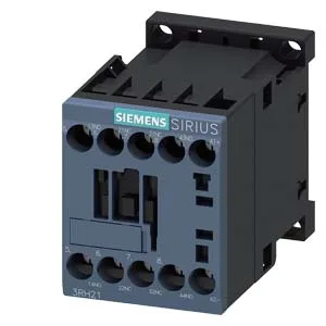
Rated for 110 V DC coil operation with an integrated suppressor diode, this variant handles the DC control voltages common in PLC-driven panels and battery-backed safety circuits. The diode suppresses the inductive kick when the coil de-energizes — no external snubber needed on the van.
Switching ratings — what they mean on the line
The contact ratings are given per voltage, not as a single blanket current. At 24 V DC it switches 10 A; at 60 V DC it drops to 4.7 A; at 110 V DC it's 3 A; at 220 V DC it's 1.2 A. This voltage-dependent derating is typical for DC switching — arc extinction is harder at higher voltage, so the contactor's capability shrinks. On the AC side at 230 V it handles 10 A, at 400 V it's 3 A, and at 690 V it's 1 A. The 10 000 switching cycles per hour at AC and the 7–20 ms arcing time at DC give a realistic duty-cycle picture for conveyor or pump control. Two instantaneous contacts (NO/NC configurable via the auxiliary switch block) handle the signal-level interlocking. The design accepts an auxiliary switch extension, so you can add more contacts without replacing the whole unit — useful when a line-down fix needs extra feedback to the PLC.
RoHS compliance is documented with a substance prohibition date of 10/01/2009, covering the EU RoHS directive.
Mounting and clearances — panel integration notes
That 6 mm side gap is the one that catches people — if you're packing contactors side-by-side, leave at least that much breathing room for heat dissipation and wiring access. Terminal capacity accepts 2x 0.5–1.5 mm², 2x 0.75–2.5 mm², or 2x 4 mm² solid or stranded. That covers most control-circuit wiring gauges on the van; no need for special ferrules unless the panel spec demands them.