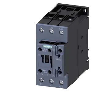
SIRIUS S2 frame — 40 A AC-3 switching for motor loads
The 3RT2035-1AM20 is a Siemens SIRIUS power contactor in the S2 frame size, rated 40 A at 480 V in AC-3 duty — the standard category for squirrel-cage motor switching. That 40 A AC-3 figure is the one that governs real motor starts; the contactor handles 1,000 operations per hour in AC-3 and AC-3e service. Coil is 208 V at 50 Hz, drawing 0.36 A holding current at 50 Hz and 0.39 A at 60 Hz. The magnet coil uses screw-type terminals, matching the main circuit termination style. Mechanical endurance is rated 10 million operations typical — this is the unloaded cycle life; electrical endurance under AC-3 load will be lower and depends on the actual switching current and frequency.
DIN rail mounting and panel clearances
Mounts via screw and snap-on onto 35 mm DIN rail per DIN EN 60715. The mounting position allows +/-180° rotation on a vertical surface and can be tilted forward/backward by +/-22.5° — useful when fitting into tight or angled panel sections. Dimensions: 55 mm wide, 114 mm high, 130 mm deep. Clearance distances for arc flash and heat dissipation: 10 mm upwards, 10 mm forwards, 10 mm downwards, and 6 mm at the side. These are the minimum free-air gaps — stacking contactors closer without derating risks thermal accumulation or phase-to-phase tracking. Conductor cross-section accepted: 2x (0.5 to 1.5 mm²) or 2x (0.75 to 2.5 mm²) solid or stranded — this covers most control-circuit wiring up to 14 AWG. The main power terminals accept larger conductors; the spec table on the product page lists the full range.
Switching duty and operating rates
Maximum operating rates vary by duty category: 1,200 ops/h in AC-1 (resistive), 1,000 ops/h in AC-3 and AC-3e (motor start/run), 750 ops/h in AC-2 (slip-ring motor), and 300 ops/h in AC-4 (plugging/inching). The AC-4 rate is the limiting factor for reversing or jogging applications. Arcing time spans 10 to 20 ms, with an AC operating time of 10 to 18 ms. These matter for coordination with upstream short-circuit protection devices — the let-through energy during arcing determines whether the fuse or breaker clears before the contactor welds.
Auxiliary contact block and ratings
The contactor includes an auxiliary switch with 1 N/O + 1 N/C configuration (18 to 1 on the main contact count). Auxiliary contact ratings: 10 A at 24 V, 2 A at 48 V, 2 A at 60 V, 1 A at 110 V, 0.9 A at 125 V, 0.3 A at 220 V, 3 A at 400 V, and 0.6 A at 440 V. These are the maximum continuous currents — derate for inductive DC loads per the application note. The 7.5 hp rating at 230 V gives a quick cross-check for North American motor sizing on single-phase applications.
Environmental range and storage
Operating temperature range is -25 to +60 °C; storage range is -55 to +80 °C. The wider storage envelope means the contactor can sit in an unheated warehouse or truck without damage, but the operating ceiling of 60 °C limits panel internal ambient — factor in heat rise from other components when grouping contactors.