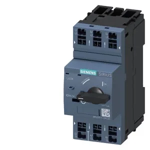
Integrator note — what this SIRIUS breaker does in the panel
No screw torque to check — just strip to the correct length and push in. That saves panel-build time and eliminates the most common field fault (loose screw terminals on a motor branch).
Mounting and clearance — panel fit
Minimum clearance to adjacent devices: 50 mm above and below, 30 mm to the side, 0 mm forward and backward. That 50 mm vertical clearance is the critical one — it allows hot gas to vent safely during a short-circuit interruption. If you cram the breaker into a tight enclosure without that 50 mm headroom, the arc gases can ionize adjacent terminals and cause a phase-to-phase fault. Mounting position is any — the breaker operates correctly upright, sideways, or inverted. That flexibility helps when laying out a dense panel; you are not forced to orient all breakers the same way.
Rated operational voltage covers 20 to 690 V AC, with the AC-3 (motor) rating going up to 690 V maximum. That means it can protect motors on 400 V, 480 V, or 690 V systems — common in North American 480 V and European 400/690 V industrial networks. At 230 V, the rated motor power is 0.1 kW — that is the maximum induction motor it can protect at that voltage. At 480 V the rated current is 0.5 A, and at 600 V also 0.5 A. These are the thermal overload settings, not the short-circuit rating — the breaker's overload element must be set to match the motor FLA. Maximum switching frequency under AC-3 duty is 15 operations per hour. That is typical for a motor-protective breaker — it is not designed for frequent on-off cycling like a contactor; it sits upstream of the contactor and only opens on fault or manual disconnect. No ground-fault or phase-failure detection built in. If your application requires those, you need an external ground-fault relay or a more advanced electronic motor-protective breaker. The -20 °C lower limit matters for unheated enclosures in cold climates — below that, the bimetal overload trip curve shifts and the breaker may not protect accurately.