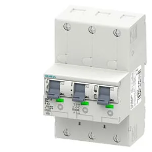
It mounts on a 40-mm busbar system per DIN 43870 Part 2, which is the standard grid for meter cabinets in European utility installations. The E tripping characteristic — rated 50 A at 400 V AC, 50 Hz — means it holds through inrush from transformer magnetizing currents or motor-starting loads better than a B or C curve, while still tripping within the 25 kA rated short-circuit capacity per EN 60898.
The solid and stranded conductor range is 2.5 to 50 mm², which covers the full cross-section from a 2.5 mm² meter tail up to a 50 mm² main feeder. The enclosure depth is 76.3 mm, which is the dimension to check for clearance in a shallow meter cabinet. Mechanical service life is 20 000 switching cycles typical. Vibration resistance per IEC 60068-2-6 is 2 g, 20 frequency cycles 5 to 150 Hz; shock resistance is 30 g, at least 3 impacts, 11 ms duration — figures that matter for transport and seismic qualification, not for normal panel operation.
Integration notes for the meter cabinet
Mounting is on a 40-mm busbar system per DIN 43870 Part 2 — not a DIN rail. The breaker occupies 4.5 width units on that busbar. Infeed is via box terminal at the top; outgoing feeder uses spring-loaded terminals. The locking device accepts a locking slide with lock, additional wire seal, cable ties, or Antilux seals — relevant for utility meter-sealing requirements. The switch position indicator shows OFF = green, ON = red. The power supply cord position is stipulated for installation in the lower section of the meter panel per the design.