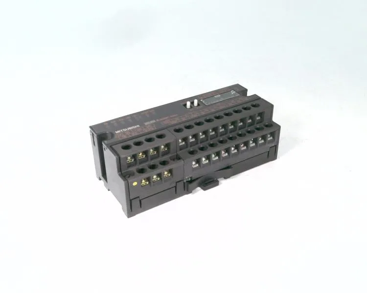
Dual analog output with 1 ms conversion per channel
The AJ65SBT-62DA is a two-channel Digital-Analog Converter Module that simultaneously outputs voltage and current signals. Voltage range spans -10 to 10 VDC into a minimum load of 2 kΩ; current range covers 0 to 20 mA into up to 600 Ω. Maximum conversion speed is 1 ms per channel, which means a full dual-channel update every 2 ms — fast enough for closed-loop process control on pumps, valves, and drives where the loop time is in the 10–50 ms range. Digital input resolution is 16-bit signed binary: -4096 to 4095 for voltage output, and 0 to 4095 for current output. That gives roughly 12.5 bits of usable resolution after the sign bit and offset — adequate for 0.1% class analog output loops, but not for high-precision applications that need true 16-bit monotonicity.
Load resistance limits and wiring constraints
The voltage output requires a minimum external load resistance of 2 kΩ. If the connected device presents a lower impedance — common with older pneumatic I/P transducers or unloaded signal conditioners — the output will droop or clip. The current output, by contrast, drives loads up to 600 Ω; a 250 Ω loop resistor (standard for 4-20 mA into a PLC analog input) leaves plenty of headroom for line resistance in long cable runs. Current consumption from the 24 VDC backplane is 0.16 A. That is light — a 2 A power supply can drive twelve of these modules. But the inrush current hits 8.2 A for the first 2.1 ms on power-up; if the rack is hot-swapped or the backplane breaker is fast-trip, that surge can nuisance-trip a 1 A PPTC fuse. Sequence power-up of multi-module racks or use a slow-blow fuse rated at least 1.5 A per module slot.
Mature lifecycle — plan for replacement
The AJ65SBT-62DA carries a 'mature' lifecycle stage, meaning Mitsubishi continues to produce it but it is past its primary sales window. No official successor order code is listed in the public record. For new designs or panel expansions, the MELSEC iQ-R series R60DA4 (four analog outputs, -10 to 10 V and 0-20 mA, 16-bit resolution) is a logical functional replacement, but it occupies 16 I/O points on the PLC versus this module's different backplane interface — a panel re-spin is required to swap families.