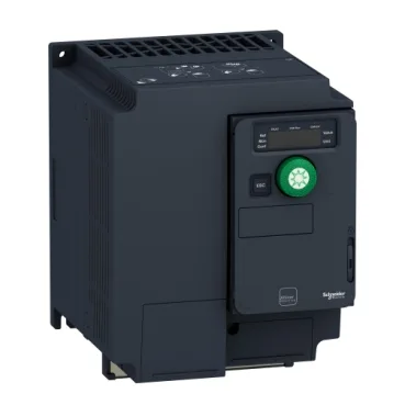
Schneider Electric ATV320U30M3C412
MPNATV320U30M3C412
Active
Variable speed drive, Altivar Solar, 3.0kW, 200 to 240V, 3 phases, compact
Source DocumentedChannel stated on listing & quote
Condition PhotosReal unit photos / video on request
WhatsApp AnswersFast human replies for machine-down parts
Worldwide DispatchDHL/FedEx — transit quoted per order
Independent China distributor & sourcing agent· Listing updated Sep 2026
Specifications
| Parameter | Value |
|---|---|
| Protection type | Input phase breaks drive Overcurrent between output phases and earth drive Overheating protection drive Short-circuit between motor phases drive Thermal protection drive |
| Range of product | Altivar Solar |
| Relay output type | Configurable relay logic R1A 1 NO 100000 cycles Configurable relay logic R1B 1 NC 100000 cycles Configurable relay logic R1C Configurable relay logic R2A 1 NO 100000 cycles Configurable relay logic R2C |
| Analogue input type | AI1 voltage 0...10 V DC 30 kOhm 10 bits AI2 bipolar differential voltage +/- 10 V DC 30 kOhm 10 bits AI3 current 0...20 mA (or 4-20 mA, x-20 mA, 20-x mA or other patterns by configuration) 250 Ohm 10 bits |
| Discrete input type | STO safe torque off, 24 V DC1.5 kOhm DI1...DI6 logic inputs, 24 V DC 30 V) DI5 programmable as pulse input 0...30 kHz, 24 V DC 30 V) |
| Analogue output type | Software-configurable current AQ1 0...20 mA 800 Ohm 10 bits Software-configurable voltage AQ1 0...10 V DC 470 Ohm 10 bits |
| Discrete output type | Open collector DQ+ 0...1 kHz 30 V DC 100 mA Open collector DQ- 0...1 kHz 30 V DC 100 mA |
| Type of polarization | No impedance |
| Product or component type | Variable speed drive |
| Maximum output voltage | 240 V |
| Supply voltage | 200...240 V - 15...10 % |
| Line current | 18.7 A 200 V heavy duty) 15.7 A 240 V heavy duty) |
All specifications
| Parameter | Value |
|---|---|
| Nominal output current | 13.7 A |
| Short-circuit protection | thermal protection |
| Maximum switching current | Relay output R1A, R1B, R1C resistive, cos phi = 1 3 A 250 V AC Relay output R1A, R1B, R1C resistive, cos phi = 1 3 A 30 V DC Relay output R1A, R1B, R1C, R2A, R2C inductive, cos phi = 0.4 7 ms 2 A 250 V AC Relay output R1A, R1B, R1C, R2A, R2C inductive, cos phi = 0.4 7 ms 2 A 30 V DC Relay output R2A, R2C resistive, cos phi = 1 5 A 250 V AC Relay output R2A, R2C resistive, cos phi = 1 5 A 30 V DC |
| Maximum transient current | 20.6 A 60 s |
| Minimum switching current | Relay output R1A, R1B, R1C, R2A, R2C 5 mA 24 V DC |
| Maximum input current per phase | 18.7 A |
| Base load current at high overload | 3.0 A |
| Power factor | 0.599 at 230 V |
| Apparent power | 6.5 kVA 240 V heavy duty) |
| Motor power | 3.0 kW heavy duty |
| Power dissipation in | Fan 105.0 W 200 V 4 kHz |
| Network frequency | 50-60 Hz |
| Switching frequency | 2...16 kHz adjustable 4...16 kHz with derating factor |
| Maximum output frequency | 0.599 kHz |
| Nominal switching frequency | 4 kHz |
| Relative symmetric network frequency tolerance | 5 % |
| IP degree of protection | IP20 |
| Communication port protocol | Modbus serial CANopen |
| Mounting mode | Wall mount |
| Electrical connection | Screw terminal 0.5...1.5 mm² analog input Screw terminal analog output Screw terminal |
| EMC filter | Without EMC filter |
| Pollution degree | 2 |
| Operating altitude | 3280.84...6561.68 ft (1000...2000 m) with current derating 1 % per 100 m <= 3280.84 ft (1000 m) without derating |
| Permitted relative humidity (during operation) | Class 3K5 according to EN 60721-3 |
| Maximum acceleration under shock impact (during operation) | 150 m/s² at 11 ms |
| Maximum acceleration under vibrational stress (during operation) | 10 m/s² at 13...200 Hz |
| Depth | 6.2 in (158.0 mm) |
| Width | 5.5 in (140 mm) |
| Height | 7.2 in (184.0 mm) |
| Standards | IEC 61800-5-1 |
| Marking | CE UR UKCA RCM |
| Variant | Standard version With disconnect switch |
| Category | US1CP4B22152 |
| Data format | 8 bits, configurable odd, even or no parity |
| Noise level | 52 dB |
| Option card | communication module, Ethernet IP/Modbus TCP |
| Assembly style | With heat sink |
| Braking torque | 170 % with braking resistor |
| Speed accuracy | +/- 10 % of nominal slip 0.2 Tn to Tn |
| Regulation loop | Adjustable PID regulator |
| Local signalling | 1 LED (red) for drive fault 1 LED (red) for CANopen error 1 LED (green) for CANopen run |
| Method of access | Slave CANopen |
| Operating position | Vertical +/- 10 degree |
| Format of the drive | Compact |
| Number of addresses | 1...247 1...127 |
| Relay output number | 2 |
| Discrete input logic | Positive logic (source) Negative logic (sink) |
| Overvoltage category | II |
| Prospective line isc | 5 kA |
| Transient overtorque | 170...200 % of nominal motor torque |
| Analogue input number | 3 |
| Braking to standstill | By DC injection |
| Discrete input number | 7 |
| Volume of cooling air | 4332.5 Gal/hr(US) (16.4 m3/h) |
| Analogue output number | 1 |
| Discrete output number | 3 |
| Motor slip compensation | Automatic whatever the load Adjustable 0...300 % Not available in voltage/frequency ratio (2 or 5 points) |
| Brake chopper integrated | True |
| Product specific application | Pumping applications |
| 4 quadrant operation possible | True |
| Electromagnetic compatibility | Electrostatic discharge immunity test level 3 conforming to IEC 61000-4-2 Radiated radio-frequency electromagnetic field immunity test level 3 conforming to IEC 61000-4-3 Electrical fast transient/burst immunity test level 4 conforming to IEC 61000-4-4 1.2/50 µs - 8/20 µs surge immunity test level 3 conforming to IEC 61000-4-5 Conducted radio-frequency immunity test level 3 conforming to IEC 61000-4-6 Voltage dips and interruptions immunity test conforming to IEC 61000-4-11 |
| With sft fct safe stop 2 (SS2) | False |
| Ambient air transport temperature | -13...158 °F (-25...70 °C) |
| Synchronous motor control profile | Vector control without sensor |
| Asynchronous motor control profile | Voltage/frequency ratio, 5 points Flux vector control without sensor, standard Voltage/frequency ratio - Energy Saving, quadratic U/f Flux vector control without sensor - Energy Saving Voltage/frequency ratio, 2 points |
| Acceleration and deceleration ramps | Linear U S CUS Ramp switching Acceleration/deceleration ramp adaptation Acceleration/deceleration automatic stop with DC injection Automatic adaptation of ramp if braking capacity exceeded, by using resistor Linear adjustable separately from 0.01 to 6000 s |
| Ambient air temperature for storage | -13...158 °F (-25...70 °C) |
| Ambient air temperature for operation | 14...122 °F (-10...50 °C) without derating 122...140 °F (50...60 °C) with derating factor |
| Environmental class (during operation) | Class 3C3 according to IEC 60721-3-3 Class 3S2 according to IEC 60721-3-3 |
| With safety function safe stop 1 (SS1) | True |
| With safety function safe position | False |
| With safety function safe direction | False |
| With safety function safe torque off | True |
| With safety function safe programmable logic | False |
| With safety function safe speed monitor | False |
| With safety function safe operating stop | False |
| With safety function safely limited speed | True |
| With safety function safely limited position | False |
| Maximum deflection under vibratory load (during operation) | 1.5 mm at 2...13 Hz |
MPN
ATV320U30M3C412