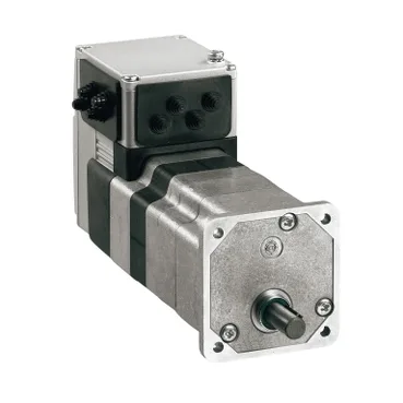
Form factor and mounting
The ILE2P661PC1A5 ships as a 229 mm-long integrated motor-and-gearhead with a 66 mm flange face, designed for flange mounting directly to the driven load. The hollow output shaft on the gear side takes a pinned or clamped coupling — there's no second shaft end, so a single shaft seal layout covers the application. An industrial connector handles power, logic, and the four bidirectional signal lines, so cabinet-side wiring lands on a single plug rather than a separate driver. Natural convection cooling means no fan cut-out or air duct to derate in a sealed enclosure — the housing dissipates on its own at the 45 W / 66 W continuous output points.
Gearing and torque envelope
Two-stage worm gearing at a 24:1 reduction drops the brushless DC motor's medium-speed winding to a 168 rpm nominal output, both at 24 V and 48 V supply. The worm form gives a non-backdrivable output by default — useful for vertical-axis loads that must hold position when the drive is de-energised, at the cost of efficiency. Continuous torque is rated at 3.8 N·m at both 24 V and 48 V; peak stall torque reaches 6.19 N·m at the same supplies, and 45 W at 24 V or 66 W at 48 V of mechanical output is on the nameplate. Detent torque from the worm geometry is 2.9 N·m — this is the residual cogging the controller must overcome at zero speed, not the load capability.
Feedback and control fidelity
Position feedback comes from the integrated BLDC encoder, and the drive is specified at ±1 point of accuracy error — the resolution that matters for a 24:1 output shaft, not the raw motor-shaft count. The encoder is read inside the integrated drive, so the fieldbus layer just consumes the resolved position over the 100 Mbit link without an external counting module. Four signals are software-configurable as input or output, letting the same wiring handle end-of-travel limits, brake release, and a status output on installations where the I/O count is modest. Built-in protection covers output short circuit, output overload, and safe torque off — the STO function is the one that satisfies the safety circuit without an external contactor.
Power, environment, and compliance
The supply window is 18–55.2 V, which makes the unit suitable for both 24 VDC and 48 VDC bus architectures on machine skids. Peak current draw is 7 A with a 5.5 A maximum continuous figure — at 48 V that lines up with the 66 W continuous output, and the wiring gauge should be sized for the peak, not the continuous average. The drive carries a CE mark and is tested to EN/IEC 61800-3 second environment, EN/IEC 50178, and the IEC 60072-1 motor frame standard — the second-environment EMC classification means it can sit on the industrial floor of a plant without the filtering upgrades a first-environment (residential) install would need. Mechanical endurance is rated at 150 m/s² for shock across 1000 shocks and 20 m/s² sweep over 10 cycles on vibration; bearing service life is 3000 hours — that's the figure that defines the preventative replacement interval on a continuously-running conveyor or indexer.
Procurement posture
The unit ships one per package with an industrial connector, so panel build quantities are quoted to order against the BOM rather than pulled from a shelf.