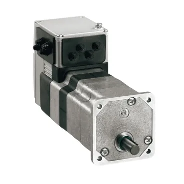
Form factor the panel has to accept
The ILE2P661PC1A7 is a Lexium integrated drive — a brushless DC servo motor and 3-stage worm gearbox packaged as one unit, sized around a 66 mm motor flange and 229 mm overall length. That integrated form is the defining feature: the drive electronics live on the back of the motor, so the assembly drops into the machine as a single flange-mounted axis rather than a motor-and-drive pair wired across the cabinet. Mounting is flange-style with a hollow shaft end and an industrial connector for the bus and I/O — the gearbox output is the only mechanical interface the machine builder has to design around. CE marked to EN/IEC 61800-3, EN/IEC 50178, EN 50347 and IEC 60072-1, so it sits in a panel built to the usual low-voltage drive practice.
Geartrain and what the output shaft actually delivers
The 92:1 reduction (735:5) turns a medium-speed brushless rotor into a low-speed, high-torque output — nominal speed is 44 rpm at both 24 V and 48 V, nominal torque 9.2 N.m, and peak stall torque 19.78 N.m on either bus voltage. For sizing, treat the 9.2 N.m figure as the continuous working point and the 19.78 N.m peak as the cap for acceleration and shock loads, not the duty rating. Nominal mechanical output is 41 W at 24 V and 42 W at 48 V — useful to know when the gearbox output runs against a holding load, because a worm gear is non-backdrivable by nature and the 108.9 lbf.in (12.3 N.m) detent torque is what keeps the axis from creeping when the bus is off. The unit ships without a second shaft end and without a holding brake.
Bus power, current draw and protection envelope
Supply is a 18 to 55.2 VDC bus on a single-phase input topology — the drive runs off a DC source (typical of the Lexium integrated line) and pulls 5500 mA maximum continuous with 7000 mA peak. At 7000 mA peak the upstream 24 V or 48 V supply needs to hold the bus above the undervoltage floor under load step; derating starts above 1000 m altitude and the ambient window is bounded by 15 to 85 % non-condensing humidity. Built-in protection covers safe torque off, output short circuit, and output overload — STO is wired on the industrial connector alongside four configurable signal lines that each serve as input or output. Cooling is natural convection only, so the 66 mm flange and surrounding enclosure volume carry the thermal budget; do not blanket-insulate the housing.
Feedback, mechanical life and environmental envelope
Position feedback is a BLDC encoder on the motor side of the gearbox with ±1 point accuracy — the closed loop closes at the high-speed rotor, not the reduced output, so backlash in the worm train lives between the encoder reading and the load. For an axis where the application needs to know where the output shaft actually sits, an external position sensor on the gearbox output is the way to read past the gear train.
Lifecycle status and how the line is sourced
For a procurement line that means the BOM position is supported; the practical question is supply posture, not part discontinuation. If the BOM needs to land fast, the call to make is the one that pins the bus voltage (24 V vs 48 V), the connector variant, and whether the gearbox output must be the 92:1 reduction or one of the other ratios in the ILE family before the order is placed.