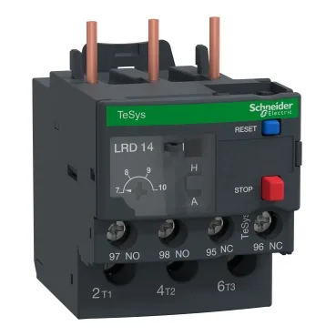
Its thermal protection adjustment range covers 7 to 10 A, with a Class 10A tripping curve that matches standard motor start profiles — meaning it allows the motor to start without nuisance tripping but still protects against sustained overloads. The relay provides one normally-open and one normally-closed auxiliary contact (1 NO + 1 NC), used to signal the overload condition back to the control circuit. The signalling circuit is rated for 3 A at 120 V AC-15 and 0.22 A at 125 V DC-13, which covers most PLC input and contactor coil loads. It complies with EN/IEC 60947-4-1 and 60947-5-1, plus UL 60947-4-1 and CSA C22.2 equivalents, so it is accepted in panels destined for North American and European installations. The IP20 finger-safe enclosure suits enclosure-mounting behind a panel door.
The 7-10 A adjustment range sets the motor full-load current (FLC) window. A motor drawing 8 A FLC lands in the middle of the range, leaving headroom for the 1.14 ± 0.06 Ir tripping threshold — the relay will trip at roughly 9.1 A after a Class 10A delay, which is the standard protection for a motor that reaches full speed within 10 seconds. Phase-failure sensitivity is built in: if one phase drops to 30 % of the set current while the other two run at Ir, the relay trips. This is the differential function that distinguishes a thermal overload relay from a simple bimetallic strip — it catches single-phasing, which is a common cause of motor burnouts in field-distributed power.
The relay mounts directly under a TeSys contactor, on a plate with specific accessories, or on a DIN rail with the correct adapter kit. Screw-clamp terminals on both power and control circuits accept the tightening torque of 1.7 N.m. The control circuit uses a red push-button for stop and a blue push-button for reset — a colour convention that helps the field technician identify the function without tracing wires. The relay is temperature-compensated from -20 to 60 °C, so the trip curve stays accurate across the operating range of a typical enclosure.