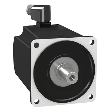
Torque envelope sized against the LXM52 / LXM62 drives
The MH31902P11F2200: Holding torque of 531.04 lbf.in (60 N.m) and continuous stall torque of 424.8 lbf.in (48 N.m) at 115–480 V three-phase define the upper mechanical ceiling the motor can hold indefinitely without motion; the 1947.2 lbf.in (220 N.m) peak stall figure is the short-duration surge during acceleration and deceleration transients, and it is the value that decides whether the motor will trip into current limiting on a fast index move. Rated nominal torque is 256.7 lbf.in (29 N.m) when paired with either the LXM52 or LXM62 drive at 400 V or 480 V three-phase, which is the operating point used for thermal sizing of the machine — duty-cycle heat rejection is sized to 29 N.m of continuous torque, not the 60 N.m holding figure. Continuous power lands at 6260 W and peak current at 114 A Irms with a continuous stall current of 30.8 A, so any sizing conversation starts from those three values: 29 N.m of usable continuous torque, 6.26 kW of continuous mechanical output, and 30.8 A of phase current the drive must deliver indefinitely without tripping.
Drive constants and rotor inertia for loop tuning
The torque constant of 1.56 N.m/A at 248 °F (120 °C) sets the conversion between commanded current and produced torque; at the 30.8 A continuous stall point the motor produces close to its 48 N.m stall torque, which is the upper bound any current-limited controller can demand. The back-EMF constant of 108.3 V/krpm governs the regenerative voltage on the DC bus during fast decel — at 2000 rpm nominal that is roughly 216 V of back-EMF, which the LXM52 or LXM62 drive must absorb through its brake chopper or external resistor to avoid DC-bus overvoltage trips.
Encoder, shaft, brake and the kit that ships with it
Feedback is a single-turn SinCos Hiperface encoder, which provides absolute position within one mechanical revolution plus sinusoidal incremental signals for high-resolution interpolation — the resolver-free Hiperface protocol is the format the LXM52 and LXM62 drives auto-detect on first power-up. The shaft is a parallel-key design, 1.5 in (38 mm) diameter with a 0.4 in (10 mm) key width and an 80 mm shaft length, terminating in rotatable right-angled connectors that let the integrator orient the power and feedback leads after the motor is bolted down. A holding brake is integrated, drawing 25 W of pull-in power — that 25 W is the steady dissipation the cabinet thermal budget has to absorb if the brake is duty-cycled at high cycle rates. The motor flange is the 190 mm international-standard pattern with 14 mm mounting holes and a 180 mm centring collar depth of 4 mm — that flange size is what determines adapter plate machining when retrofitting into a machine that was originally laid out around a different servo frame. IP65 sealing on the body suits plant environments with coolant splash and light washdown, but it does not cover the connector face when unmated, so the cable set must carry its own sealing or the rating is voided at the wet end. Cooling is natural convection only — no fan, no liquid — so any enclosure that traps heat around the motor body derates the 6.26 kW continuous figure.
Radial load envelope across the speed range
Permissible radial force on the shaft end drops from 3200 N at 1000 rpm to 2950 N at 4000 rpm, so a belt or pinion mounted directly on the shaft has a load budget that shrinks as the line speed rises — at 2000 rpm nominal the rating is 3100 N, which is the value the mechanical designer should use when sizing a timing-belt pull or a pinion tooth load. The shaft is a parallel-key design without a second shaft end, so any auxiliary encoder or hand-crank mounts on the non-drive end of the machine, not on the motor.