Where this motor drops into the line
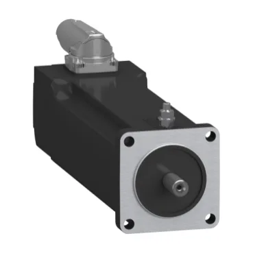
The Schneider Electric SH30553P0AA4000 is an SH3-series brushless servo motor sized around a 55 mm international-standard flange, built for the auxiliary axes of a packaging, pick-and-place, or indexing line where the drive electronics already speak Hiperface DSL. With no holding brake specified it suits applications where the load is back-driven only on a controlled stop or where the upstream gearbox holds position — adding brake hardware later requires a different variant on the same SH30553P sizing reference. Its continuous output is 680 W on three-phase 400 V or 480 V and 390 W on 230 V single phase, so the panel-side decision is whether the cabinet is laid out for three-phase feed or single-phase — running a three-phase-rated motor on single phase drops the available shaft power by roughly 40 percent without any fault indication on the drive.
Torque, speed and the 4000-to-9000 rpm envelope
Nominal torque is 1.1 N.m at 230 V single phase and 0.81 N.m at 400 V or 480 V three phase, with nominal speeds of 4000 rpm at 230 V, 8000 rpm at 400 V and 9000 rpm at 480 V. The 9000 rpm ceiling at 480 V matches the 9000 rpm maximum mechanical speed, so the motor is not field-weakened above base speed on the 480 V supply — the headroom is for transient overshoot during deceleration, not for steady-state field weakening. The continuous stall current of 1.7 A and Irms maximum of 6.5 A mean the drive sizing is set by the 3-second peak rather than the continuous figure — undersizing the drive on the Irms rating is the usual commissioning surprise.
Rotor inertia and the drive tuning window
Back-EMF constant is 41 V/krpm at 20 °C and torque constant is 0.62 N.m/A at 120 °C, so a rough current-to-torque check at the terminals is 0.62 × I_rms — useful when the drive flags a torque-limit fault and the integrator needs to confirm the demand is realistic before chasing a wiring issue. Stator resistance is 10.4 Ohm and inductance is 13.02 mH, which together define the electrical time constant the drive uses for field-oriented control.
Encoder, shaft and the quicklock connector
The feedback is an absolute single-turn Hiperface DSL encoder wired through a quicklock rotatable right-angled connector — DSL runs the encoder data and the power stage over the same cable pair to a compatible Lexium drive, which is what removes the separate encoder cable from the cabinet-to-machine run. The shaft is a 9 mm smooth shaft with a 20 mm length, so any coupling or pulley has to clear a 9 mm bore with a setscrew or clamp-style fixing — keyed shafts are a different variant.
Mounting, axial and radial load limits
The motor flange is the international-standard 55 mm pattern with four 5.5 mm mounting holes, a 40 mm centring collar and 2 mm collar depth. Maximum radial force is 660 N at 1000 rpm and maximum axial force is 80 N, both of which are the figures to check when the application uses a belt or a pinion — over-running the radial limit at the shaft end is the most common premature-bearing failure on this class of servo.
Sealing, cooling and panel-side integration
The motor body carries IP65 protection to IEC 60034-5 and the shaft bushing carries IP54 without a shaft seal ring — the IP65 rating covers hose-directed water and dust ingress for washdown-adjacent zones, but the shaft entry is the weak point if the line uses a wet environment past the shaft seal. Cooling is natural convection, so the motor must be mounted with the housing clearances the manual specifies; shrouding the body inside an enclosure derates continuous torque by roughly the percentage the manual calls out.
Sourcing posture for the BOM line
No official L*-recorded successor or P*-recorded peer carries a different catalogue code in the ledger, so no cross-reference is named on this page.