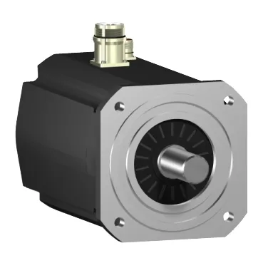
Where this motor sits in the BOM
The SH32051P01F1000 is a three-phase AC servo in the SH3 family with a 205 mm international-standard flange mount and a 14.6 in (370.5 mm) frame length, so it drops into the standard servo footprint used across packaging, converting, and material-handling lines. Holding torque lands at 708.06 lbf.in (80 N.m) with a peak stall ceiling of 973.6 lbf.in (110 N.m), which sets the mechanical envelope a gearbox or direct-drive coupling must respect on the machine side.
Voltage taps and what the speed/torque envelope actually delivers
Nominal speed scales with the drive bus: 750 rpm on 115 V single-phase, 1500 rpm on 230 V single-phase, 3000 rpm on 400 V three-phase, and 3600 rpm on 480 V three-phase — so the same motor spans low-voltage North American cells and 400/480 V three-phase cabinets without a different frame. Nominal output power follows the same ladder, peaking at 5500 W on 400 V three-phase and 5200 W on 480 V three-phase, with 2510 W and 4240 W on the 115 V and 230 V single-phase taps respectively. Nominal torque drops with speed in the expected hyperbolic pattern: 282.3 lbf.in (31.9 N.m) at 115 V single-phase down to 122.1 lbf.in (13.8 N.m) at 480 V three-phase, which is the figure that sizes the continuous working point on the machine, not the holding torque ceiling. Continuous stall torque is 326.6 lbf.in (36.9 N.m) against a 21 A continuous stall current, and the maximum Irms ceiling is 87.2 A — those two numbers together fix the thermal operating window the drive must respect at zero speed.
Feedback, brake, and electrical interface
A holding brake is integrated into the motor — useful for vertical axes where the load must hold position with the drive de-energised — and power is brought out through a straight connector rather than a flying lead.
Mechanical fit: shaft, flange, and thrust loads
The shaft is a smooth 1.5 in (38 mm) diameter, 3.1 in (80 mm) long, matched to a 180 mm centring collar with 0.2 in (4 mm) depth and 14 mm mounting holes on the international standard flange. Maximum mechanical speed is 3800 rpm, so any application pushing the 480 V nominal point of 3600 rpm has only a narrow margin before the mechanical ceiling is reached and bearing life becomes the limiting factor.
Thermal and electrical constants the drive must respect
Cooling is natural convection — no integrated fan — so the continuous torque figures assume a panel that lets the body radiate; an enclosed cabinet or a coupling into a hot gearbox will pull the continuous working point down. Stator resistance is 0.3 Ohm with 8.7 mH inductance, and the back-EMF constant is 104 V/krpm at 20 °C — the drive sizing tool uses these to predict bus ripple current at the target speed.
Procurement posture and how to specify it
Lifecycle status is recorded as current on the SH32051P01F1000, so this is a live BOM position rather than a last-time-buy — volumes are quoted to order against the RFQ with lead time and price confirmed at quote time, and the landed cost picture depends on the HS code and Incoterm rather than the list figure. The order code follows the SH32051P01 sizing reference with the F1000 variant suffix indicating the encoder, brake, and connector combination — match the F-suffix to the drive commissioning file before releasing the PO, because the brake and feedback options are encoded there.