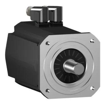
Schneider Electric SH32051P01F2000 — Servo Motors with Brake

SH32051P01F2000 SH3 Servo Motor, 80 N.m, 5500 W, IP65

MPNSH32051P01F2000
Obsolete

Schneider Electric SH3 series servo motor SH32051P01F2000, 80 N.m holding torque, 5500 W continuous power, IP65, Hiperface SinCos absolute encoder, 205 mm flange, with holding brake.

StockContact for availability
MOQ1 pcs
Sourced new & surplus through independent channelsAuthenticity-screened · ESD-safe packingListing updated Jul 2026
How we verify every order →

Specifications

Identification

SH32051P01F2000 — Identification
ParameterValue
Product typeServo motor
Holding brakeWith

Performance

SH32051P01F2000 — Performance
ParameterValue
Nominal torque282.3 lbf.in (31.9 N.m) 115 V single phase 239.0 lbf.in (27 N.m) 230 V single phase 154.9 lbf.in (17.5 N.m) 400 V three phase 122.1 lbf.in (13.8 N.m) 480 V three phase
Nominal output power2510 W 115 V single phase 4240 W 230 V single phase 5500 W 400 V three phase 5200 W 480 V three phase
Continuous power5500 W
Nominal speed750 rpm 115 V single phase 1500 rpm 230 V single phase 3000 rpm 400 V three phase 3600 rpm 480 V three phase
Maximum mechanical speed3800 rpm
Continuous stall torque326.6 lbf.in (36.9 N.m) 115...480 V three phase
Peak stall torque973.6 lbf.in (110 N.m) 115...480 V three phase
Holding brake torque708.06 lbf.in (80 N.m)
Rotor inertia87.4 kg.cm²

Electrical

SH32051P01F2000 — Electrical
ParameterValue
Rated supply voltage (Us)115...480 V
Network phases3
PhaseThree phase
Maximum current (Irms)87.2 A
Continuous stall current21 A
Torque constant1.75 N.m/A 248 °F (120 °C)
Back-EMF constant104 V/krpm 68 °F (20 °C)
Number of motor poles5.0
Stator resistance0.3 Ohm
Stator inductance8.7 mH
Electrical connectionRotatable right angled connector

Feedback

SH32051P01F2000 — Feedback
ParameterValue
Encoder typeAbsolute single turn SinCos Hiperface
Speed feedback resolution128 periods

Mechanical

SH32051P01F2000 — Mechanical
ParameterValue
Shaft end styleSmooth shaft
Shaft diameter1.5 in (38 mm)
Shaft length3.1 in (80 mm)
Motor flange size8.07 in (205 mm)
Mounting supportInternational standard flange
Length14.6 in (370.5 mm)
Number of mounting holes4
Mounting-hole diameter0.6 in (14 mm)
Mounting-hole bolt circle diameter8.5 in (215 mm)
Centring collar diameter7.09 in (180 mm)
Centring collar depth0.2 in (4 mm)
Maximum radial force (Fr)3730 N 1000 rpm 2960 N 2000 rpm 2580 N 3000 rpm
Maximum axial force (Fa)740 N

Environmental

SH32051P01F2000 — Environmental
ParameterValue
IP degree of protectionIP54 shaft bushing without shaft seal ring: conforming to IEC 60034-5 IP65 motor: conforming to IEC 60034-5 IP65 shaft bushing: conforming to IEC 60034-5
Cooling methodNatural convection
Winding (copper hot) temperature266 °F (130 °C)

Product details

Torque envelope and what 80 N.m actually buys you

The SH32051P01F2000: Torque constant sits at 1.75 N.m/A at the 120 °C copper-hot reference, which is the slope a drive uses to translate commanded current into shaft torque — useful when sizing the drive's continuous current against this motor's torque demand.

Speed-power scaling across supply rails

Continuous output power runs 2510 W at 115 V single-phase, 4240 W at 230 V single-phase, 5500 W at 400 V three-phase, and 5200 W at 480 V three-phase, so the 400 V three-phase rail is the natural target when the application wants full 5.5 kW continuous — falling back to single-phase sacrifices roughly half the available continuous power. Maximum current is 87.2 A rms (same value given for the 3-second peak output current), and stator resistance is 0.3 Ohm with 8.7 mH stator inductance — these are the winding parameters the drive's auto-tuning routine reads at first commissioning.

Encoder, brake, and what 'with holding brake' changes mechanically

Cooling is natural convection with no external fan — there is no auxiliary blower supply to wire, but the continuous torque rating already assumes a free-air mount with adequate clearance on the housing surface for heat rejection.

Sealing, flange, and shaft-side integration

Mounting is an international standard flange at 205 mm (8.07 in) with a 180 mm centring collar (4 mm depth) and 14 mm mounting holes — the flange footprint and centring collar are the geometry a gearbox or machine-base adapter must match. The shaft is a 38 mm (1.5 in) diameter smooth shaft, 80 mm (3.1 in) long, with a rotatable right-angled connector at the electrical side — the connector orientation can be set on assembly to keep the cable exit clear of the adjacent coupling or gearbox housing. Maximum radial load on the shaft is 3730 N at 1000 rpm, 2960 N at 2000 rpm, 2580 N at 3000 rpm; maximum axial load is 740 N — these are the bearing-life limits a belted or geared coupling must respect, with the radial limit dropping as speed rises. Back-EMF constant is 104 V/krpm at 20 °C — this is the figure the drive uses to clamp overvoltage on a deceleration event, and it dictates the minimum bus voltage needed to reach a given no-load speed.

Frequently asked questions

What is SH32051P01F2000's listed phase on this component line?

The listing states three-phase for SH32051P01F2000, which matches the 400 V / 480 V operating points at 3000 and 3600 rpm nominal speed.

MPN
SH32051P01F2000