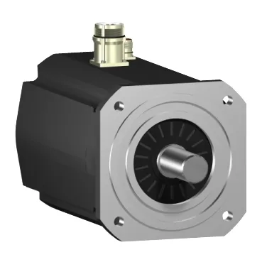
Sizing the SH32052P02A1200 to the drive it lands on
Nominal output scales with the DC bus the drive delivers: 3230 W at 115 V single phase climbs to 5860 W at 230 V single phase, peaks at 7980 W on 400 V three phase, and steps back to 7140 W at 480 V three phase — so the same motor frame drops roughly 10 % continuous power when fed from a 480 V rectifier versus a 400 V one, and the integrator needs to confirm the drive's nominal bus voltage before locking the BOM line. Continuous power is listed at 7900 W, and the peak stall torque of 220 N·m is the figure that defines the short-cycle overload budget — paired with the 96.8 A Irms/3-second peak, it tells the drive sizing engineer the peak current the amplifier must source without tripping.
Mechanical integration: flange, shaft, and shaft loads
Mounting is via an international standard flange with a 205 mm motor flange size, a 180 mm centring collar seated 4 mm deep, and four 14 mm mounting holes — the standard footprint mates with NEMA-style and IEC flange adapters without an adapter plate. The shaft is a smooth 38 mm diameter × 80 mm long — a heavy-duty profile sized for direct coupling to gearboxes or large-diameter pulleys without a keyway, and the feedback device is an absolute multiturn SinCos Hiperface encoder feeding back to a Lexium-series drive over the standard Hiperface protocol. Shaft loading is the figure most often missed at the BOM stage: maximum radial force Fr is 4200 N at 1000 rpm, dropping to 3330 N at 2000 rpm and 2910 N at 3000 rpm, while maximum axial force Fa is 740 N — these are the bearing-life limits, not just catalogue numbers, and a belted drive with overhung load needs to be checked against the curve at the actual operating rpm. Sealing per IEC 60034-5 is IP65 on the motor body and IP67 on the housing, with IP65 on the shaft bushing — adequate for washdown-adjacent zones and outdoor cabinets, but not full IP69K, so high-pressure food-grade cleaning duty still calls for an external shroud.
Thermal and electrical envelope
Cooling is natural convection, so the continuous torque derates with mounting attitude and any shrouding of the motor body — the 130 °C copper-hot limit is the thermal ceiling, and the continuous stall current of 25.7 A at 64.9 N·m continuous stall torque is the zero-rpm operating point the drive must respect to keep the winding within that thermal budget. Stator resistance is 0.3 Ohm and inductance 2.95 mH, with a back-EMF constant of 161 V/krpm at 20 °C and a torque constant of 2.52 N·m/A at 120 °C — the back-EMF figure is what determines the safe top speed under field-weakening, since the drive's DC bus ceiling minus back-EMF has to stay above zero across the speed range. Nominal speed steps with supply: 500 rpm at 115 V single phase, 1000 rpm at 230 V single phase, 2000 rpm at 400 V three phase, 2400 rpm at 480 V three phase — and nominal torque tracks the inverse curve, from 61.6 N·m at 115 V down to 28.4 N·m at 480 V, because output power P = T·ω is approximately preserved across the voltage steps.
Production status and how to put it on the BOM
Length is 405 mm for cabinet-fit planning, and the connector is a straight connector on the motor face — the long body is consistent with the SH32052 frame's high-inertia rotor and means the integrator should verify axial clearance against adjacent panels before committing the layout.