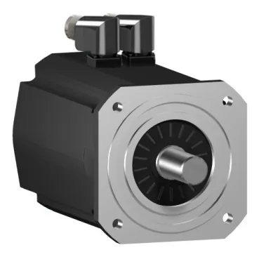
SH3 frame, 205 mm flange, Hiperface feedback — what the part is
The SH32052P02A2100 is a member of the SH3 AC servo family, with an 8.07 in (205 mm) international-standard flange and an 180 mm centring collar that bolts directly into the standard servo mounting footprint. There is no holding brake on this build, which is the configuration you specify when the load cannot free-wheel past the coupling under a power-loss event.
Voltage-dependent torque and power envelope
Nominal torque and output power track the supply the drive is fed, not a single flat figure: at 115 V single phase the motor delivers 545.2 lbf.in (61.6 N.m) at 500 rpm and 3230 W continuous; at 230 V single phase it reaches 495.6 lbf.in (56 N.m) at 1000 rpm and 5860 W; at 400 V three phase it produces 337.2 lbf.in (38.1 N.m) at 2000 rpm and 7980 W; at 480 V three phase the rating is 251.4 lbf.in (28.4 N.m) at 2400 rpm and 7140 W. The 400 V three-phase point is the rated maximum continuous power of 7980 W and the operating point the catalog headline number is taken at — sizing a 400 V bus drive around 7.98 kW mechanical output is correct; sizing a 115 V single-phase drive around the same number overstates the available shaft power by roughly 2.5×.
Peak torque, continuous stall and current ceiling
Continuous stall torque is 574.4 lbf.in (64.9 N.m) at a continuous stall current of 25.7 A, so any application that sits near stall speed for more than a few seconds has to be derated to that floor. Maximum Irms and the 3-second peak output current are both 96.8 A — the drive current limit setpoint and the I²t trip in the controller must be configured against that ceiling rather than the nominal current, otherwise the drive will fault on the first hard acceleration pulse.
Drive-loop electrical constants
The torque constant is 2.52 N.m/A at 248 °F (120 °C) winding temperature, which is the working-point figure — not a 25 °C value — so any closed-loop torque estimate has to use it as published. Back-EMF constant is 161 V/krpm at 68 °F (20 °C); the drive's DC-bus voltage ceiling sets the maximum safe no-load speed through that constant. Stator resistance is 0.3 Ohm and stator inductance is 2.95 mH, which feed the current-loop bandwidth tuning and the short-circuit protection coordination on the drive side.
Mechanical envelope and shaft load ratings
The shaft is 1.5 in (38 mm) diameter with a 3.1 in (80 mm) length, smooth (no keyway) — couplings and pinions have to be clamp-style or shrink-fit, not keyed. Mounting holes are 0.6 in (14 mm) diameter on the standard flange pattern and the centring collar is 7.09 in (180 mm) diameter by 0.2 in (4 mm) deep — the bolt circle and pilot fit the SH3 family footprint without adapter plates.