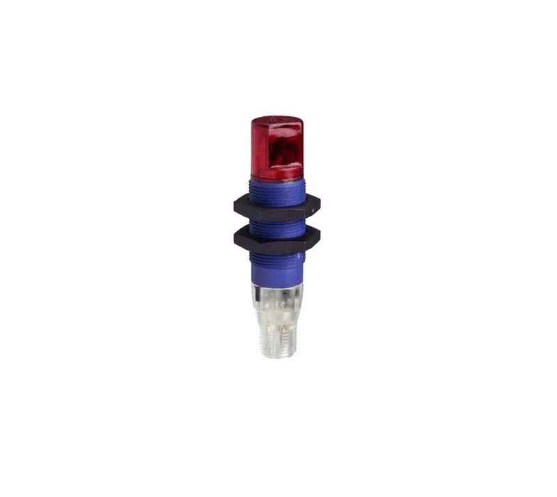
The Telemecanique XUB4BPAWM12 is a fixed proximity diffuse photoelectric sensor in the OsiSense XUB family, built for presence detection of opaque objects at a fixed 4-inch range. The 18 mm nickel-plated brass threaded barrel and IP67 / NEMA 4X/12 enclosure mean it handles washdown environments and outdoor exposure on packaging lines, conveyor transfer stations, or material-handling equipment. A 90-degree side-sensing orientation lets it mount flush against a bracket and detect objects passing perpendicular to the barrel axis — useful where space above the target is restricted. Output is PNP normally-open, solid-state, switching 100 mA max at 12–24 VDC. The 1 ms on/off response time and 500 Hz switching frequency keep up with fast-moving product on a moderate-speed line — think bottle filling or carton indexing, not high-speed servo pick-and-place. The yellow LED on the body confirms output state for commissioning and troubleshooting without a scope.
What the 4-inch diffuse range means for fit
Four inches (about 100 mm) is a short-range diffuse detection zone. The sensor emits infrared and relies on the target's reflectivity to return enough light to trigger the output. That means the actual usable range depends on the object's color, surface finish, and angle — a matte black carton at 4 inches may not reliably trigger, while a white or reflective surface at the same distance will. For consistent detection, mount the sensor so the target passes within 3 to 3.5 inches of the face; the 4-inch figure is the maximum under ideal conditions (90% reflectance white card per IEC 60947-5-2). The 90-degree side-sensing position means the optical axis exits perpendicular to the barrel axis, not out the front face. When replacing a front-sensing diffuse sensor, check the bracket geometry — the XUB4BPAWM12 may require a different mounting hole orientation or a right-angle bracket to aim the beam correctly.
Connection and wiring
The 4-pin micro connector (M12 industry standard) accepts a mating cordset — no cable is attached to the sensor body. Three wires are active: brown (12–24 VDC), blue (0 VDC common), and black (PNP NO output). The fourth pin is unused on this 3-wire configuration. Wiring is straightforward: pull 24 VDC to pin 1, common to pin 3, and the output signal to pin 4 of the mating connector. Verify the load does not exceed 100 mA; the solid-state output has no mechanical contacts to weld, but overcurrent damages the driver transistor.