What it is and what it does
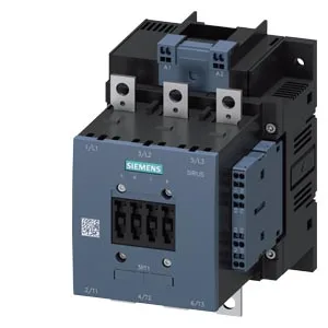
The Siemens 3RT1054-2AS36 is a SIRIUS power contactor in frame size S6, designed for switching motor loads in industrial control panels. It carries a rated control supply voltage of 500...550 V AC at 50/60 Hz, with a pull-in power factor of 0.8 at both frequencies — meaning the inrush on the coil circuit is predictable across line supplies. The contactor is fixed via screw mounting through a single 9 mm hole, and the mounting position is flexible: it can be rotated ±90° on a vertical surface or tilted ±22.5° forward and back. This matters when you're fitting it into a tight panel layout where the busbar or gland plate forces an orientation change. The coil connects through spring-type terminals (push-in style), while the main power circuit accepts stranded cable from 25 to 120 mm² — a wide range that covers most motor feeds up to the S6 frame limit. Auxiliary wiring uses a separate spring terminal accepting 2x 0.25...2.5 mm² solid or stranded.
Ratings that drive the selection
Switching frequency varies by duty class: 800 operations per hour under AC-1 (resistive loads), 1,000 ops/h under AC-3 (standard squirrel-cage motor starting), and 130 ops/h under AC-4 (plugging/inching). The AC-3e rating matches the AC-3 figure at 1,000 ops/h — so if you're running a European motor with IEC efficiency class, the contactor handles the same cycle rate. The AC-4 limit is the one to watch: if your application does frequent reversing or inching, 130 ops/h is the ceiling before the contacts wear prematurely. Mechanical endurance is rated at 10 million operations typical, which is standard for the SIRIUS S6 class. The contactor includes an auxiliary switch, rated at 10 A at 24 V DC, 2 A at 48 V and 60 V DC, and 1 A at 110 V DC — useful for feeding a PLC input or a status lamp on the panel door. Operating temperature range is -25 to +60 °C, with storage from -55 to +80 °C — so it can sit in an unheated warehouse or a hot enclosure near a furnace line. The contactor dimensions are 172 mm high, 120 mm wide, 170 mm deep; clearance requirements are 10 mm upward, 10 mm downward, 20 mm forward, and 10 mm at the side for arc dissipation and airflow.