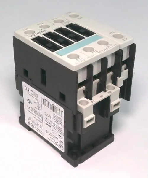
It is rated for 7.5 kW at 400 V in AC-2 duty, which covers slip-ring motor starting and reversing — the kind of load that demands higher switching frequency than a standard AC-3 contactor handles. The coil pulls 24 V at 50 Hz, holding at 7.8 VA once sealed. Screw-type terminals on both the main and auxiliary circuits keep wiring straightforward for panel builders who prefer a proven termination over spring-cage novelty. Side-by-side mounting is allowed, which matters when you are packing multiple contactors into a tight enclosure row.
That is the motor power this contactor can switch under slip-ring duty, where the current peaks during starting but stays within the contactor's thermal capacity. For resistive loads (AC-1), the same contactor carries 10 A at 24 V, 6 A at 230 V, and 3 A at 400 V — these are the continuous current limits for heaters or lighting banks. The coil holding power is 7.8 VA, a modest draw that keeps the control transformer sizing reasonable when multiple contactors are held in simultaneously.
Coordination and wiring
For type 2 coordination (no welding after a short circuit), Siemens specifies a gL/gG fuse of 25 A. For type 1 coordination (welding allowed, but no fire or shock hazard), the fuse rating jumps to 63 A. These are the values to hand to the panel designer when sizing the branch circuit protection. The main circuit accepts solid conductors from 0.5 to 4 mm² (two per terminal) and stranded up to 6 mm² (two per terminal), with a maximum of 10 mm² for a single conductor. AWG equivalents run from 20 to 12 for the main contacts.