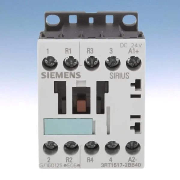
Siemens 3RT1517-2BB40 — Contactors

Siemens 3RT1517-2BB40 SIRIUS Power Contactor, 24 VDC, S00

MPN3RT1517-2BB40

Siemens SIRIUS power contactor, size S00, 24 V DC coil, 12 A rated current, spring-loaded terminals, 45 x 60 x 72 mm, screw and snap-on DIN rail mounting.

$85.73Ref. price · indicative, final on quote
Sourced new & surplus through independent channelsAuthenticity-screened · ESD-safe packingListing updated Jul 2026

Specifications

3RT1517-2BB40 — Identification
ParameterValue
Contactor frame sizeS00
3RT1517-2BB40 — Ratings & Performance
ParameterValue
Rated operational current, AC-12, max.10 A
Rated value @ 400 V3 A
Rated value @ 230 V6 A
Rated value @ 24 V10 A
Rated value @ 60 V2 A
Rated value @ 110 V1 A
Rated value @ 220 V0.3 A
3RT1517-2BB40 — Control & Coil
ParameterValue
Control supply voltage typeDC
3RT1517-2BB40 — Contacts & Poles
ParameterValue
Main poles4
Main NO contacts2
Auxiliary contact reliability1 faulty switching per 100 million (17 V, 1 mA)
3RT1517-2BB40 — Protection & Coordination
ParameterValue
Short-circuit coordination type 1, fusefuse gL/gG: 35 A
Short-circuit coordination type 2, fusefuse gL/gG: 20 A
Aux. switch short-circuit protection, fusefuse gL/gG: 10 A
3RT1517-2BB40 — Connection & Mounting
ParameterValue
Main circuit connectionspring-loaded terminals
Aux. / control circuit connectionspring-loaded terminals
Conductor cross-section, solid2x (0.25 ... 2.5 mm²)
Conductor cross-section, solid or stranded2x (0,25 ... 2,5 mm²)
Conductor cross-section, finely stranded w/ ferrule2x (0.25 ... 1.5 mm²)
Mounting methodscrew and snap-on mounting onto 35 mm standard mounting rail according to DIN EN 50022
Side-by-side mountingYes
3RT1517-2BB40 — Durability
ParameterValue
Durability (operating cycles, typ.)30 000 000
Durability with aux. switch block (cycles, typ.)10 000 000
3RT1517-2BB40 — Environmental
ParameterValue
Operating temperature range-25 ... +60 °C
Storage temperature range-55 ... +80 °C
Installation altitude, max.2 000 m
3RT1517-2BB40 — Mechanical
ParameterValue
Width45 mm
Height60 mm
Depth72 mm

Product details

The contactor uses spring-loaded terminals for both the main current circuit and the auxiliary/control circuit, accepting 2x (0.25 to 2.5 mm²) solid or stranded wire.

The 12 A rating per NO/NC contact is the continuous thermal current (Ith) — the contactor can carry 12 A continuously without exceeding temperature rise limits. This is the figure to match against your load current, not a switching rating. For DC switching of auxiliary contacts, the ratings drop significantly with voltage: 10 A at 24 V, 2 A at 60 V, 1 A at 110 V, 0.3 A at 220 V, and 0.8 A at 440 V. The minimum DC switching capability is 0.01 A at 24 V — below that, the contacts may not reliably break the arc. The coil pickup is guaranteed at 85% of rated voltage (20.4 V for a 24 V coil) and dropout at 110% (26.4 V), so a sagging 24 V bus below 20.4 V will cause the contactor to drop out.

It occupies a 45 mm width, 60 mm height, and 72 mm depth — a compact S00 footprint.

Frequently asked questions

What are the key ratings for this contactor?

The main contact continuous current is 12 A per pole. The coil is 24 V DC. The auxiliary contacts are rated for DC switching: 10 A at 24 V, 2 A at 60 V, 1 A at 110 V, 0.3 A at 220 V, and 0.8 A at 440 V. The impulse withstand voltage is 6 kV for both main and auxiliary circuits.

What wire sizes does the spring-loaded terminal accept?

It accepts 2x (0.25 to 2.5 mm²) solid or stranded wire, or 2x (24 to 14 AWG).

What is the mounting footprint?

The contactor is size S00: 45 mm wide, 60 mm high, 72 mm deep. It mounts on 35 mm DIN rail per DIN EN 50022, screw or snap-on.

What compliance documentation is available?

The RoHS substance prohibition date is 01.07.2006. The short-circuit protection recommendation is a 20 A gL/gG fuse for type of coordination 2.

MPN
3RT1517-2BB40