SIRIUS S0 power contactor — what fits and what doesn't
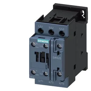
The Siemens 3RT2025-1AD20-1AA0 is a SIRIUS-branded power contactor in the S0 frame size, designed for switching motor loads in control panels. It carries a 24 VDC coil and screw-type terminals for both main and auxiliary contacts, with an integrated auxiliary switch block. The S0 frame means it occupies 45 mm of DIN-rail width and stands 85 mm tall — a standard footprint that drops into most European-style panels without re-drilling gland plates. Rated for 1,000 operating cycles per hour under AC-1, AC-2, AC-3, and AC-3e duty, this contactor handles continuous switching of resistive and motor loads. The AC-4 rating drops to 300 cycles/h — that's the wear limit for plugging or inching duty, so if your application reverses the motor under load, expect shorter contact life at higher frequencies. Mechanical life is rated at 10 million operations, which is typical for the S0 frame class. The operating temperature range of -25 to +60 °C covers most indoor panel environments, while storage tolerance from -55 to +80 °C means it survives cold warehouses and hot shipping containers without issue.
Mounting and wiring — DIN rail clearance
Mounts via screw or snap-on onto 35 mm standard mounting rail per DIN EN 60715. The standing position on a horizontal mounting surface is specified — don't lay it on its side without checking the manufacturer's derating curves. Clearance requirements: 10 mm upwards, 10 mm forwards, 10 mm downwards, and 6 mm at the side. That 6 mm side gap is tight — adjacent devices on the same rail need that much breathing room for heat dissipation. Main contact terminals accept solid or stranded conductors from 1 to 10 mm². For fine-stranded wire, the spec allows 2x (0.5 to 1.5 mm²) or 2x (0.75 to 2.5 mm²) — useful when paralleling control wiring. The coil connection uses screw-type terminals, so keep a PZ1 bit handy for termination.
Auxiliary contact ratings — what it switches on the control side
The built-in auxiliary switch is rated for 10 A at 24 V, 2 A at 48 V, 2 A at 60 V, 1 A at 110 V, 0.9 A at 125 V, 0.3 A at 220 V, and 0.6 A at 440 V. At 400 V it's rated 3 A. These are the make-and-break capacities for the auxiliary contacts — useful for PLC inputs, relay coils, or indicator lamps. The 230 V rating is given as 3 hp, which is the motor load the auxiliary can switch directly.
Coil and arcing characteristics
Coil holding current is 0.25 A at 50 Hz and 0.28 A at 60 Hz — the DC coil on this variant doesn't have a holding current spec listed, but the AC values give a sense of the inrush if you're sizing a control transformer for a mixed AC/DC panel. Arcing time is listed as 4 to 16 ms with a tighter 10 to 10 ms figure — the spread likely reflects load-dependent variation.