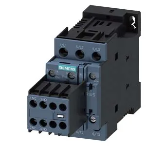
The 3RT2027-1BB44: The 24 VDC coil draws 6 A at its rated value, which is the inrush current to pull the armature in. The coil operating range is 0.8 to 1.1 times the rated voltage, so it will pick up reliably at 19.2 VDC and hold in up to 26.4 VDC. This is a standard control voltage for industrial DC buses, common in PLC-driven panels. The main contacts are rated for AC-3 duty (squirrel-cage motor switching) at 750 operating cycles per hour maximum, and AC-1 (resistive) at 1,000 cycles per hour. For the most demanding AC-4 duty (inching/plugging), the maximum is 250 cycles per hour. These limits govern the thermal load on the contact tips — exceeding them accelerates wear, especially on AC-4 where the contacts make and break under full motor current. For DC switching, the contactor is rated at 6 A at 24 V, 2 A at 48 V and 60 V, 1 A at 110 V, 0.9 A at 125 V, 0.3 A at 220 V, and 3 A at 400 V. These are the maximum resistive currents the contacts can interrupt at those voltages — DC arcs are harder to extinguish than AC, so the ratings drop sharply as voltage rises. The motor rating at 230 V is 5 hp, which gives a quick sizing reference for typical North American motor loads on a 230 V single-phase or three-phase supply.
This allows installation in tight or awkward panel orientations without derating. Physical dimensions are 85 mm height, 45 mm width, and 151 mm depth. These are minimum air gaps for arc flash and heat dissipation — crowding the contactor reduces its effective switching life. Wire range for the main and coil terminals: solid or stranded 1 to 10 mm², or two conductors of 0.5 to 1.5 mm² or 0.75 to 2.5 mm². The screw-type terminals are standard for panel wiring — no special crimp tools needed, but torque to the manufacturer's specification (not listed here) for reliable connection.
Operating Conditions and Lifecycle
The operating temperature range covers most indoor industrial environments; the wide storage range allows for unheated warehouses or shipping in extreme climates. The dropout delay is the time from coil power removal to main contact opening — important for sequencing in safety circuits or when coordinating with upstream breakers.
Configuration Notes
This variant has no auxiliary switch block integrated — the auxiliary switch is listed as 'No'. If you need auxiliary contacts for status feedback or interlocking, you will need to order a separate auxiliary contact block (e.g., the 3RT29 series) that clips onto the front or side of the S0 contactor. The main contact configuration is listed as '16... 8', which typically indicates the contact arrangement for a 3-pole contactor with normally open main contacts. This is the standard for motor starting — three NO poles for the motor circuit.