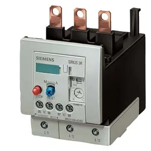
Mounts directly onto a contactor via the fastening method listed as contactor mounting — no DIN rail required, which saves rail space in a crowded panel. Dimensions are 120 mm high, 70 mm wide, and 140 mm deep. That zero-clearance spec on five of six sides means you can pack relays tight without derating for airflow — the heat dissipation (4 W per pole) is handled through the contactor base.
Main circuit terminals are screw-type, accepting 2× (10…50 mm²) stranded or 10…70 mm² single conductor, or 2× (10…1/0) AWG. Auxiliary and control circuit terminals are Cage Clamp (spring-cage), accepting 2× (0.5…2.5 mm²) solid or 2× (20…14) AWG. The mixed terminal types mean the power wiring gets a high-torque screw connection while the control wiring gets a vibration-resistant spring clamp — no tool change needed for the aux side.
For Type 1 coordination (no damage to the relay under fault, but the contactor may need replacement), a gG fuse of 160 A is required upstream. For Type 2 coordination (relay and contactor survive the fault), a gG fuse of 63 A is required.
Relative humidity during operation can reach 100% (condensation allowed, but the IP20 front means the relay must be inside a sealed enclosure for wet environments). Shock resistance is 8 g for 10 ms — sufficient for most industrial machinery but not for high-G mobile equipment.
The built-in auxiliary contacts are rated for switching: 1 A at 24 V, 0.22 A at 110 V, 3 A at 120 V, 0.22 A at 125 V, 0.11 A at 220 V, 2 A at 230 V, and 1 A at 400 V.