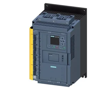
Hazardous-area soft starter with integrated fieldbus
The Siemens 3RW5527-3HF04 is a soft starter carrying ATEX and IECEx certification, meaning it can be installed in Zone 2 or Zone 22 hazardous areas where flammable gases, vapors, or combustible dust may be present under abnormal conditions. Rated for 200-480 V supply, it covers the common low-voltage motor range across Europe (400 V) and North America (480 V), with UL and CSA approvals confirming acceptance in NEC and CEC installations. The unit integrates Modbus RTU, Modbus TCP, and EtherNet/IP natively, plus PROFIBUS and PROFINET via optional communication modules, so it drops into most control architectures without a gateway.
Trip class selection and motor protection
Configurable trip classes — CLASS 10A, 10E (default), 20E, or 30E per IEC 60947-4-2 — let the starter match the thermal withstand of the motor and driven load;. The safe state is defined as an open load circuit, which on a fault removes power from the motor — this aligns with fail-safe behavior expected in SIL-rated loops, though the unit itself carries one fail-safe channel. A B10d value of 1,000,000 operations means the mechanical switching element is suitable for high-cycle applications where the probability of dangerous failure per demand must be quantified, typical in safety-related motor start/stop sequences.
Process features for pump and conveyor duty
Pump ramp down gradually reduces torque on pump stop, eliminating the fluid hammer that damages pipework and valves in long suction or discharge lines — a standard feature, not an add-on option. Torque control and breakaway pulse handle high breakaway torque loads such as belt conveyors or screw feeders: the pulse delivers a timed torque spike to overcome static friction, then the ramp takes over. DC braking provides a DC injection to the motor windings for rapid, controlled stopping without a separate brake resistor — useful on conveyors where coast-to-stop is unacceptable. Analog output configurable for 4-20 mA or 0-10 V lets a PLC or DCS read motor current or torque in real time, feeding condition-monitoring or process-control loops.
Panel integration and clearance requirements
Dimensions 306 mm high × 185 mm wide × 203 mm deep — the unit occupies a standard enclosure footprint but requires 100 mm clearance above, 75 mm below, 10 mm in front, and 5 mm on each side for airflow; zero clearance needed at the back. Screw terminals are not used — the power and control connections are likely spring-cage or ring-lug, so the panel builder must have the correct crimp tool and ferrule kit on hand.