| Open circuit leakage current | 0.1mA / DC30V |
|---|
| Input OFF sensitivity current | 1.5mA or less |
|---|
| Power fuse | 250V 5A |
|---|
| Power consumption | 65W |
|---|
| DC24V service power | 460mA or less |
|---|
| External power supply | DC5 ~ 30V |
|---|
| DC5V internal supply power supply | 290mA |
|---|
| Allowable momentary power failure time | 10ms will continue to operate for the momentary power failure follows. If the power supply voltage is AC200V system, by the user program, you can change it to 10 ~ 100ms. |
|---|
| Frequency | 57 ~ 150Hz : Acceleration: 9.8m / s2 X, Y, Z each direction 10 times (for a total of each 80 minutes) criteria, according to IEC61131-2 |
|---|
| Rated frequency | 50 / 60Hz |
|---|
| Maximum frequency | 20kHz |
|---|
| I/O channels | 64 points |
|---|
| 1 phase 1 count input | [C235, C236] up to two points: the best 60kHz high speed compared to SET / RESET when using: 10kHz high-speed bandwidth comparing HSZ use at the time: 5.5KHz [C237 ~ C245] up to 4 points: up to 10kHz high speed compared to SET / RESET when using: 10kHz high speed bandwidth comparing HSZ use at the time: 5.5kHz high-speed counter, pulse output instruction, the sum of the frequency at which the sequencer pulse density instruction processing (2-phase counter are totaled twice the input frequency) is a 20kHz maximum. During the high-speed comparison SET / RESET use, high-speed counter, pulse output instruction, the sum of the frequency at which the sequencer pulse density instruction processing (2-phase counter are totaled twice the input frequency) is the maximum 11kHz is. High-speed counter, pulse output instruction, the sum of the frequency at which the sequencer processes a pulse density instruction (the two-phase counter summing up the 2 times the input frequency), 5.5kHz is the maximum. |
|---|
| 1-Phase 2-Count input | [C246] up to one point: the best 60kHz high speed compared to SET / RESET when using: 10kHz high-speed bandwidth comparing HSZ use at the time: 5.5KHz [C247 ~ C250] up to two points: the best 10kHz high speed compared to SET / RESET when using: 10kHz high-speed bandwidth comparing HSZ use at the time: 5.5kHz high-speed counter, pulse output instruction, the sum of the frequency at which the sequencer pulse density instruction processing (2-phase counter are totaled twice the input frequency) is a 20kHz maximum. During the high-speed comparison SET / RESET use, high-speed counter, pulse output instruction, the sum of the frequency at which the sequencer pulse density instruction processing (2-phase counter are totaled twice the input frequency) is the maximum 11kHz is. High-speed counter, pulse output instruction, the sum of the frequency at which the sequencer processes a pulse density instruction (the two-phase counter summing up the 2 times the input frequency), 5.5kHz is the maximum. |
|---|
| 2-Phase 2-Count input | [C251] up to one point: the best 30kHz high speed compared to SET / RESET when using: 5kHz high-speed bandwidth comparing HSZ use at the time: 4kHz [C252 ~ C255] up to two points: the best 5kHz high speed compared to SET / RESET when using: 4kHz high-speed bandwidth comparing HSZ when using: 4kHz high-speed counter, pulse output instruction, the sum of the frequency at which the sequencer pulse density instruction processing (2-phase counter are totaled twice the input frequency) is a 20kHz maximum. During the high-speed comparison SET / RESET use, high-speed counter, pulse output instruction, the sum of the frequency at which the sequencer pulse density instruction processing (2-phase counter are totaled twice the input frequency) is the maximum 11kHz is. High-speed counter, pulse output instruction, the sum of the frequency at which the sequencer processes a pulse density instruction (the two-phase counter summing up the 2 times the input frequency), 5.5kHz is the maximum. |
|---|
| Direct mounting at the time | Frequency: 10 ~ 57Hz : Half amplitude: 0.075mm X, Y, Z each direction 10 times (for a total of each 80 minutes) criteria, according to IEC61131-2 |
|---|
| Input connection shape | Removable terminal block (M3 screws) |
|---|
| Output connection shape | Removable terminal block (M3 screws) |
|---|
| Response time | OFF ON : Y000, Y001: 15 s following Y002 later: 0.2ms or less |
|---|
| Input response time | About 10Ms X000 ~ X017 (to basic unit built-in number) it has a built-in digital filter, can be changed in 1ms unit to 0 ~ 60ms depending on the application instructions or D8020. If 0 is specified, X000, X001 is 20 s, X002 ~ X017 will be 50 s. |
|---|
| Operating temperature | 0 ~ 55 °C ····· operation, -20 ~ 70 °C ····· during storage |
|---|
| Relative humidity | 35 ~ 85% RH (non-condensing) ..... operation |
|---|
| Vibration resistance | When the DIN rail mounting : Frequency: 10 ~ 57Hz : Half amplitude: 0.035mm X, Y, Z each direction 10 times (for a total of each 80 minutes) criteria, according to IEC61131-2 |
|---|
| Shipping weight | 2.8 Kg |
|---|
| 10ms | T200 ~ T245 46-point (0.01 to 327.67 seconds) |
|---|
| State | Initial state : S0 ~ S9 10 points |
|---|
| Device | Input and output relay : Input relay : X000 ~ X267 184 points (octal number) extension when used with |
|---|
| Ground | Class D grounding (ground resistance: 100 or less) <common ground is not allowed with the high-voltage system> ground, please dedicated ground or shared ground. |
|---|
| Impact | 147m / s2, duration of action 11ms, X at half-sine pulse, Y, Z 3 times each direction criterion, according to IEC61131-2 |
|---|
| ON OFF | Y000, Y001: 30 s following Y002 later: 0.2ms or less |
|---|
| Counter | 16-bit up : C0 ~ C99 100 points (0 to 32,767 counts) is a non-battery backup area. You can change the battery backup area by the parameter setting. |
|---|
| Nesting | [Master control] N0 ~ N7 8 points (for MC instruction) |
|---|
| Pointer | JUMP, for CALL branch : P0 ~ P127 128 points (CJ instruction, for the CALL instruction, for the END jump P63) |
|---|
| Constant | Decimal number (K) : 16-bit: -32,768 + 32,767 32-bit: -2,147,483,648 ~ + 2,147,483,647 |
|---|
| For keep | S500 ~ S899 400 points is a battery back-up area. You can change to a non-battery backup area by the parameter setting. |
|---|
| Peak load | Resistance load : Output 1 point / common: 0.5A or less output 4 points / common: 0.8A or less Output 8 points / common: 1.6A or less (Y000, Y001 is, 0.3A / output 1 point) |
|---|
| Anti-noise | Noise voltage 1,000Vp-p, noise width 1 s, due to rising 1ns, cycle 30 ~ 100Hz of noise simulator |
|---|
| For special | M8000 ~ M8255 256 points |
|---|
| Total score | Less than 256 points (at the time of expansion in combination) |
|---|
| Advanced use | 2000m or less can not be used in the pressurized environment to more than atmospheric pressure. There is a possibility of failure. |
|---|
| Input format | Sink / source |
|---|
| Manufacturer | Mitsubishi Electric |
|---|
| Output relay | Y000 ~ Y267 184 points (octal number) extension when used with |
|---|
| X010 or later | More than 3.5mA |
|---|
| Inductive load | 12W / DC24V (Y000, Y001 is 7.2W / DC24V) |
|---|
| Program memory | The maximum memory capacity : 16000 step comment, 16000 steps, including the file register |
|---|
| Use atmosphere | Corrosive, there is no flammable gas, conductive dust (dust) that is not terribly |
|---|
| Auxiliary relay | For general use : M0 ~ M499 500 points is a non-battery backup area. You can change the battery backup area by the parameter setting. |
|---|
| For annunciator | S900 ~ S999 100 points is a battery back-up area. You can change to a non-battery backup area by the parameter setting. |
|---|
| For general use | S10 ~ S499 490 points is a non-battery backup area. You can change the battery backup area by the parameter setting. |
|---|
| Hexadecimal | 16-bit: 0 ~ FFFF 32 bit: 0 ~ FFFFFFFF |
|---|
| Input impedance | X000 ~ X007 : 3.3k |
|---|
| Input interrupt | I00 ~ I50 6 points |
|---|
| Real-time clock | Clock function : Built from 1980 to 2079 years (with leap year correction) The year 2-digit / 4-digit switch , monthly deviation ± 45 seconds (25 °C) |
|---|
| Timer interrupt | I6 ~ I8 3 points |
|---|
| For 16-bit index | V0 ~ V7, Z0 ~ Z7 16 points |
|---|
| Timer (on-delay) | 100ms : T0 ~ T199 200 points (0.1 to 3,276.7 seconds) |
|---|
| Counter interrupt | I010 ~ I060 6 points (for HSCS instruction) |
|---|
| 16 bit for special | D8000 ~ D8255 256 points |
|---|
| Circuit insulation | Photocoupler |
|---|
| High-speed counter | [32-bit high-speed up / down] C235 ~ C255 maximum six points usable in one phase: 60KHz, 10KHz 2 phase: 30kHz, 5kHz There is a limit to the number and input frequency that can be used by the conditions used. It is a battery backup area. You can change to a non-battery backup area by the parameter setting. |
|---|
| Estimated lead time | Usually ships in 1 - 10 working days. |
|---|
| Input signal format | No-voltage contact input sink Input: NPN open collector transistor Source Input: PNP open collector transistor |
|---|
| Protective function | There is password protection function (by keyword function) |
|---|
| Programming language | Sequence program |
|---|
| 32-Bit Bi-Directional | C200 ~ C219 20 points (-2,147,483,648 ~ + 2,147,483,647 count) is a non-battery backup area. You can change the battery backup area by the parameter setting. |
|---|
| Insulation resistance | When performing the insulation resistance test, please go between the ground terminal of each terminal and the basic unit at a voltage of below. Power supply terminal (AC power) and between the ground terminal: DC500V 5M more in insulation resistance tester DC24V service power supply, and the input terminal (DC24V) and between the ground terminal: DC500V 5M more in insulation resistance tester and the output terminal (transistor) ground terminal between: DC500V 5M more in insulation resistance tester |
|---|
| Input operation display | Input ON when the LED lights up |
|---|
| Input and output points | Number of inputs : 184 points or less (at the time of expansion in combination) |
|---|
| Positioning instruction | · ABS current value read ([D] ABS) corresponding with V3.00 or more |
|---|
| Application instructions | 1.52 to the number of 100 s / instruction |
|---|
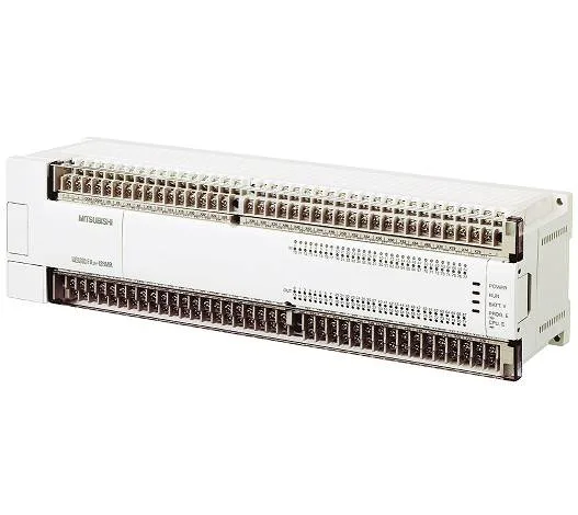
| Corresponding basic unit | Transistor output type basic unit |
|---|
| Input circuit insulation | Photocoupler |
|---|
| Output operation display | Photocoupler drive when LED lighting |
|---|
| Pulse output instruction | Pulse output (PLSY) , acceleration and pulse output with speed (PLSR) pulse output format: pulse train (the direction is controlled by the sequence) |
|---|
| Number of controlled axes | Independent 2-axis |
|---|
| Arithmetic processing speed | Basic instruction : 0.08 s / instruction |
|---|
| RUN during the write function | Yes (can change programs during the sequencer RUN) |
|---|
| Remote i (O points (CC-Link)) | Following the actual I / O, including 256 points |
|---|
| Memory cassette (memory board) | · FX-RAM-8 (2000/4000/8000/16000 step correspondence possible) · FX-EPROM-8 (2000/4000/8000/16000 step correspondence possible) · FX-EEPROM-4 (2000/4000 step correspondence possible) · FX-EEPROM-8 (2000/4000/8000 step correspondence possible) · FX-EEPROM-16 (2000/4000/8000/16000 step correspondence possible) |
|---|
| 16-Bit up (Battery backup area) | C100 ~ C199 100 points (0 to 32,767 counts) is a battery back-up area. You can change to a non-battery backup area by the parameter setting. |
|---|
| Input and output control method | Batch processing method (END when the instruction is executed), input and output refresh command, Pulse catch function |
|---|
| The arithmetic and control system | Stored program repeat operation method (dedicated LSI), there interrupt instruction |
|---|
| Built-in memory capacity and format | 8000 step RAM (backed up by a built-in lithium battery) |
|---|
| For keep (battery backup fixed area) | M1024 ~ M3071 2048 points is the battery backup fixed area. This area is characteristic not be changed. |
|---|
| 16 bit for keep (battery backup area) | D200 ~ D511 312 points is a battery back-up area. You can change to a non-battery backup area by the parameter setting. |
|---|
| Data register (32-bit in the pair used) | 16-bit general purpose : D0 ~ D199 200 points is a non-battery backup area. You can change the battery backup area by the parameter setting. |
|---|
| 16 bit for keep (battery backup fixed area) | D512 ~ D7999 7488 points (D1000 later, Allowed set to file register in the 500-point unit) is a battery backup fixed area. This area is characteristic not be changed. |
|---|
| 32-Bit Bi-Directional (Battery backup area) | C220 ~ C234 15 points (-2,147,483,648 ~ + 2,147,483,647 count) is a battery back-up area. You can change to a non-battery backup area by the parameter setting. |
|---|
| Function expansion memory (function expansion memory board) | The sequencer version V3.00 or higher, FX2N-ROM-E1 form function expansion memory board can be mounted short-mail transmission function inverter operation control function -16000 step EEPROM (2000/4000/8000 step also correspondence possible) |
|---|