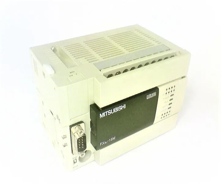
FX3U-16MR/DS - Mitsubishi Electric
MPNFX3U-16MR/DS
FX 3 U series FX 3 U - 16 MR / DS
$399.00 – $912.57Ref. price · indicative, final on quote
Source DocumentedChannel stated on listing & quote
Condition PhotosReal unit photos / video on request
WhatsApp AnswersFast human replies for machine-down parts
Worldwide DispatchDHL/FedEx — transit quoted per order
Independent China distributor & sourcing agent· Listing updated Sep 2026
Specifications
| Parameter | Value |
|---|---|
| 1 | T256 to T511 256 points (0.001 to 32.767 seconds) |
| 10 | T200 to T245 46 points (0.01 to 327.67 seconds) |
| Output type (format) | Relay output |
| 1 ms integration type | T246 to T249 4 points (0.001 to 32.767 seconds) Battery backup fixed area. Area property change is impossible. |
| 100 ms integration type | T250 to T255 6 points (0.1 to 3,276.7 seconds) Battery backup fixed area. Area property change is impossible. |
| Voltage | DC 24V |
| Withstand voltage | When performing the withstand voltage test, make the voltage between each terminal and the ground terminal of the basic unit as follows. Between power supply terminal (DC power supply) and earth terminal: 500 VAC for 1 minute Between output terminal (relay) and earth terminal: AC 1.5 kV 1 min |
| Input signal voltage | DC 16.8 to 28.8 V |
| Voltage tolerance range | DC 16.8 to 28.8 V When the power supply voltage is DC 16.8 to 19.2 V, the number of connectable devices can be reduced. |
| Inrush current | Maximum 35 A less than 0.5 ms / 24 VDC |
| Input OFF sensitivity current | 1.5 mA or less |
| Input signal current x000 to x007 | X000 ~ X005: 6mA / DC24V X006, X007: 7mA / DC24V |
All specifications
| Parameter | Value |
|---|---|
| Input ON sensitivity current x000 to x007 | X000 to X005: 3.5 mA or more X006, X007: 4.5 mA or more |
| Power consumption | It is the value when maximum is consumed by the I / O extension block added to the 25 W basic unit or the special expansion unit / block. |
| Power supply fuse | 250 V 3.15 A |
| External power supply | DC 30 V or less, AC 240 V or less (CE, UL , AC 250 V or less when not compliant with cUL standard) |
| DC 5 v internal power supply | 500 mA or less Can not be used externally. This is the power supply capacity to be supplied to the I / O expansion block, special expansion block, special adapter and function expansion board. |
| Allowable momentary power outage time | Operation continues with an instantaneous blackout of 5 ms or less. |
| Frequency | 57 to 150 Hz : Acceleration: 9.8 m / s 2 X, Y, Z 10 times in each direction (80 minutes in total) The criteria are based on IEC 61131-2 |
| Direct installation frequency | 10 to 57 Hz : One amplitude: 0.075 mm X, Y, Z 10 times in each direction (80 minutes in total) The criteria are based on IEC 61131-2 |
| Anti-vibration when DIN rail is installed frequency | 10 to 57 Hz : One amplitude: 0.035 mm X, Y, Z 10 times in each direction (80 minutes in total) The criteria are based on IEC 61131-2 |
| 1 phase 1 count input | [C235 to C240] Up to 6 points: Up to 100 kHz High Speed ??Comparison When using SET / RESET: 40 kHz High Speed ??Band Comparison When using HSZ: 40 - (Instruction Usage Count) [C244 (OP), C245 (OP)] Maximum 2 Points: 10 kHz High Speed ??Comparison When using SET / RESET: 10 kHz High Speed ??Band Comparison When using HSZ: 40 - (Instruction Used Count) [C241 ~ C245] Up to 3 Points: Up to 40 kHz High Speed ??Comparison When using SET / RESET: 40 kHz High Speed ??Band Comparison When Using HSZ>: 40 - (number of times of instruction use) High speed comparison When using SET / RESET, 80 kHz is the maximum for the sum of the frequencies processed by the sequencer (2 phase 4 quadruple counter is combined with 4 times the input frequency). High-Speed ??Band Comparison When using the HSZ, the frequency obtained by "the number of times of use of 80 kHz - 1.5 X HSZ instruction" is the maximum as the sum of the frequencies processed by the sequencer (2 - phase quadruple counter is 4 times the input frequency). |
| 1 phase 2 count input | [C246, C248 (OP)] Up to 2 points: Up to 100 kHz High Speed ??Comparison When using SET / RESET: 40 kHz High Speed ??Band Comparison When using HSZ: 40 - (Instruction Used Count) [C247 ~ C250] Up to 2 Points: Up to 40 kHz High Speed ??Comparison When using SET / RESET: 40 kHz High Speed ??Band Comparison When using HSZ: 40 - (Instruction Used Count) High Speed ??Comparison Total frequency processed by the sequencer when using SET / RESET (2 phase 4 multiplier counter adds 4 times the input frequency ) Is the maximum at 80 kHz. High-Speed ??Band Comparison When using the HSZ, the frequency obtained by "the number of times of use of 80 kHz - 1.5 X HSZ instruction" is the maximum as the sum of the frequencies processed by the sequencer (2 - phase quadruple counter is 4 times the input frequency). |
| 2 phase 2 count input | [C251, C253] Up to 2 points: Up to 50 kHz (1 multiplication, 4 multiplication) High speed comparison When using SET / RESET (1 multiplication): 40 kHz High speed comparison When using SET / RESET (4 multiplication): 10 kHz High speed band comparison When HSZ is used (1x): 40- (instruction number of uses) fast bandwidth comparing HSZ use (quadruple) :( 40- instruction usage count) ÷ 4 [C252, C253 (OP), C254, C255] up to two points: highest 40kHz fast compared SET / RESET is used (1x): 40 kHz High-speed comparison SET / RESET is used (multiplied by 4): 10 kHz High-speed bandwidth comparing HSZ use (1x): 40- (instruction number of uses) fast bandwidth comparing HSZ use (4 multiplication): (40 - instruction usage count) ÷ 4 High Speed ??Comparison When using SET / RESET, 80 kHz is the maximum for the sum of the frequencies processed by the sequencer (2 phase 4 quadruple counter is 4 times the input frequency). High-Speed ??Band Comparison When using the HSZ, the frequency obtained by "the number of times of use of 80 kHz - 1.5 X HSZ instruction" is the maximum as the sum of the frequencies processed by the sequencer (2 - phase quadruple counter is 4 times the input frequency). |
| AnyWire bitty | (3) 128 or less * Total remote I / O of CC-Link, AnyWire Bitty, AnyWireASLINK is 256 or less |
| AnyWireASLINK | (3) 128 or less * Total remote I / O of CC-Link, AnyWire Bitty, AnyWireASLINK is 256 or less |
| Input connection shape | Fixed terminal block (M3 screw) |
| Output connection shape | Fixed terminal block (M3 screw) |
| Input response time | Approximately 10 ms X000 to X017 (up to basic unit built-in number) has a built-in digital filter and can be changed in 0 ms to 60 ms in 1 ms unit according to application instructions or D8020. When set to 0, it becomes the following. X000 to X005: 5 μs X 006, X 007: 50 μs |
| Response time OFF → ON | About 10 ms |
| Operating temperature | 0 to 55 ° C. ... Operating, -25 to 75 ° C. ..... Save |
| Use altitude | Can not be used in an environment pressurized to 2000 m or less under atmospheric pressure. It may break down. |
| Relative humidity | 5 to 95% RH (noncondensing).... in operation |
| Shipping weight | 2 Kg |
| AS-i | (3) 248 or less |
| Ground | Class D grounding (grounding resistance: 100 Ω or less)Grounding should be dedicated ground or common ground. |
| Nesting | [For master control] N 0 to N 7 8 points (for MC command) |
| ON → OFF | About 10 ms |
| For keeping | M500 to M1023 524 You can change the keeping / nonkeeping setting with the point parameter. |
| String ("") | It is specified by the character enclosed by "". Up to 32 single-byte characters can be used as an instruction constant |
| Total score | (1) + (2) + (3) Total: 384 points or less (when adding together) |
| Input format | Sink / source |
| Manufacturer | Mitsubishi Electric |
| Minimum load | DC 5 V 2 mA (reference value) |
| Output relay | Y000 to Y367 248 points (octal number) When added and used |
| For keeping 1 | S500 to S899 Keep / nonkeep setting can be changed by 400 point parameter. |
| For keeping 2 | S1000 to S4095 This is a 3096 point battery backup fixed area. Area property change is impossible. |
| Inductive load | 80VA |
| Noise immunity | Noise voltage with 1,000 Vp-p, noise width 1 μs, rising 1 ns, with noise si |
| Use atmosphere | There is no corrosive property, flammable gas, conductive dust (dust) is not serious |
| For general use | S10 to S499 Keep / non-keep setting can be changed by 490 point parameter. |
| Hexadecimal | 16 bits: 0 to FFFF 32 bits: 0 to FFFFFFFF |
| Real number | 32 bits: -1.0 X 2 128 to -1.0 X 2 - 126 , 0, 1.0 X 2 - 126 to 1.0 X 2 128 Decimal point representation and exponential representation are possible |
| Special purpose | M8000 to M8511 512 points |
| Timer interrupt | I6□□ - I 8□□ 3 points |
| 16 bit up | C100 to C199 100 points (0 to 32,767 counts) Keep / nonkeep setting can be changed by parameter. |
| 32 bit up / down | C200 to C219 20 points (-2, 147, 483, 648 to +2, 147, 483, 647 counts) You can change the keeping / nonkeeping setting by parameter. |
| For 16 bit index | V 0 to V 7, Z 0 to Z 7 16 points |
| For annunciators | S900 - S999 You can change the keeping / nonkeeping setting with 100 point parameters. |
| Counter 16 bit up | C0 to C99 100 points (0 to 32,767 counts) You can change the keeping / nonkeeping setting by parameter. |
| Counter interrupt | I010 to I060 6 points (for HSCS instruction) |
| Impact resistance | 147 m / s 2 , working time 11 ms, criterion for judgment three times in X, Y, Z directions by sine half-wave pulse is according to IEC 61131-2 |
| 16 bit special use | D 8000 to D 8511 512 points |
| Circuit insulation | Mechanical insulation |
| Extension register | [16 bits] R 0 to R 32767 32768 points Battery backup fixed area. Area property change is impossible. |
| For 16 bit keeping | D200 to D511 312 points It is possible to change the keeping / nonkeeping setting by the parameter. |
| High speed counter | [32-bit high-speed up / down (keep)] C235 ~ up 8 points in C255 Usable hardware counter 1 phase: 100kHz, 10 kHz 2 phase: 50 kHz (1 multiplication), 50 kHz (4 multiplication) software counter 1 phase: 40 kHz 2 phases: 40 kHz (1 multiplication), 10 kHz (4 multiplication) There are limitations on the points that can be used and the input frequency depending on the conditions to be used. |
| Estimated lead time | Usually ships in 1 - 10 working days. |
| Input signal format | No-voltage contact input At sink input: NPN open collector transistor Source input: PNP open collector transistor |
| Protection function | With password protection function (by keyword function) |
| State initial state | S 0 ~ S 9 Keep / nonkeep setting can be changed by 10 point parameter. |
| Programming language | Relay symbol method + step ladder method (SFC expressible) |
| Insulation resistance | When conducting the insulation resistance test, perform the following voltage between each terminal and the ground terminal of the basic unit. Between power supply terminal (DC power supply) and earth terminal: 500 VDC DC insulation resistance meter 5 MΩ or more Output terminal (relay) and earth terminal: 500 VDC with insulation resistance meter 5 MΩ or more |
| Extended file register | [16 bits] ER 0 to ER 32767 32768 Only available when a memory cassette is installed. |
| Number of input points | 8 points |
| Application instruction | 0.642 μs to several 100 μs / instruction |
| Input operation display | LED ON when input is ON |
| Number of output points | 8 points |
| Timer (on-delay) 100 | T0 to T191 192 points (0.1 to 3,276.7 seconds) |
| Input circuit insulation | Photocoupler insulation |
| Memory cassette (option) | [Ver.3.00 or later] . FX3U - FLROM - 1M (2000/4000/8000/16000/32000/64000 steps supported Yes Loader function available, source information can be stored in dedicated area 1300 kbytes) [Ver.2.20] . FX3U - FLO-64L (2000/4000/8000/16000/32000/64000 step supported loader function available) . FX3U - FLROM - 64 (2000/4000/8000/16000/32000/64000 steps supported Yes Loader function not available) . FX3U - FLROM-16 (2000/4000/8000/16000 steps supported Yes No loader function) |
| Arithmetic control method | Stored program iterative calculation method (dedicated LSI), interrupt function available |
| Write function during RUN | Yes (program changeable during sequencer RUN) |
| Maximum load resistive load | 2A or less / Total load current per common per output should be as follows. Output 1 point / 1 common: 2A or less Output 4 points / 1 common: 8 A or less Output 8 points / 1 common: 8 A or less |
| Output operation indication | When the relay coil is energized LED on the panel is lit |
| Constant decimal number | 16 bits: -32,768 to + 32,767 32 bits: -2, 147, 483, 648 to +2, 147, 483, 647 |
| Input impedance x000 to x007 | X000 to X005: 3.9 kΩ X 006, X 007: 3.3 kΩ |
| Input (output control method) | Batch processing method (when END instruction is executed), I / O refresh command, with pulse catch function |
| Pointer JUMP, for CALL branch | P 0 to P 4095 4096 points (for CJ instruction, CALL instruction, P 63 for END jump) |
| Real time clock clock function | Built-in 1980 to 2079 (with leap year correction) 2-digit year / 4-digit switchable, monthly difference ± 45 seconds (25 ° C) |
| Device i (O relay input relay) | X000 to X367 248 points (octal number) When added and used |
| Auxiliary relay for general use | M 0 ~ M 499 500 points You can change the keeping / nonkeeping setting by parameter. |
| For 16-bit keep (file register) | D 512 to D 7999 7488 points (It can be set as file register in units of 500 points after D 1000, it is a battery backup fixed area. Area property change is impossible. |
| Keep (battery backup fixed area) | M1024 to M7679 6656 points Battery backup fixed area. Area property change is impossible. |
| Internal memory capacity (format) | 64000 steps (source information storable Yes Ver. 3.00 or higher) / RAM memory (backed up with built-in lithium battery) Battery life: About 5 years |
| Number of remote i (O points CC-Link) | (3) 256 points or less (224 points or less when using FX2N - 16 CCL - M) * The total of remote I / O of CC - Link, AnyWire Bitty, AnyWireASLINK is 256 or less |
| Input interrupt, input delay interrupt | I00□ ~ I50□ 6 points |
| Program memory maximum memory capacity | 64 thousand step comment, 64000 steps including file register |
| Types of instructions basic instruction | [Ver 2.30 or later] - Sequence instruction 29 pieces - Step ladder instructions 2 pieces [Ver. 2.30 or less] - Sequence instruction 27 pieces - Two step ladder instructions |
| Arithmetic processing speed basic instruction | 0.065 μs / Instruction |
| 100 ms (For subroutines and interrupt routines) | T192 to T199 8 points (0.1 to 3,276.7 seconds) |
| Number of input (output points number of input points) | (1) 248 points or less (when adding together) (1) + (2) Total: 256 points or less |
| Data register (32 bits in pair use) for 16-bit general purpose | D0 ~ D199 The setting of keeping / nonkeeping can be changed by 200 point parameter. |
MPN
FX3U-16MR/DS