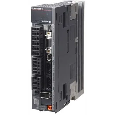
What it is and what it drives
The Mitsubishi MR-J4-350A is a 1-axis servo amplifier from the MELSERVO-J4 series, sized for a 3.5 kW servo motor on a 200 V class three-phase supply. The 17.0 A output rated current tells you the continuous current it can deliver to the motor under rated load — that's the number to match against your motor's nameplate current, not the 0.2 A control-circuit draw. The built-in dynamic brake means the amplifier can stop the motor quickly on a fault or STO event without an external braking resistor for most inertial loads, though you'll still need one for high-inertia or vertical-axis applications where regenerative energy exceeds the internal shunt capacity.
Power and wiring
Main power comes in as three-phase AC 200 V to 240 V, 50/60 Hz, with allowable fluctuation from 170 V to 264 V — so it handles a saggy line without dropping out. The control circuit needs a separate single-phase AC 200 V to 240 V supply plus a 24 V DC ±10% logic supply that must deliver at least 0.5 A for the CN8 connector signals. That 24 V rail is often overlooked in panel builds; if your existing cabinet only has a 24 V bus rated for PLC loads, confirm it has headroom for this additional 0.5 A draw before you land the wires.
Control and feedback
The amplifier uses sinusoidal-wave PWM current control, which gives smooth torque at low speeds and reduces audible motor noise compared to trapezoidal drives. The 22-bit encoder resolution — that's 4,194,304 pulses per revolution after quadrature — gives you fine position feedback for precision indexing or contouring. For multi-axis coordination, the RS-422/485 port supports up to 32 axes in a 1:n daisy chain, which is useful for gantry or multi-axis pick-and-place cells where you want one controller talking to all drives over a single serial line.
Setup and monitoring
Configuration is done over USB using Mitsubishi's MR Configurator2 software — no special programming tool needed, just a standard USB cable to a laptop. The two analog monitor channels let you output speed, torque, or position signals as DC voltages for scope viewing or feeding into a PLC analog input for real-time monitoring. The general-purpose command interface accepts analog speed commands (0 to ±8 V for max torque) or internal speed commands selectable via parameter.