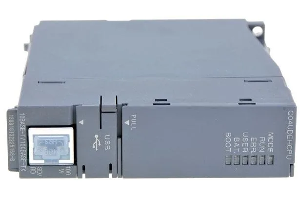
Mitsubishi Q04UDEHCPU MELSEC-Q CPU Module
MPNQ04UDEHCPU
Mitsubishi (217900) Universal Q CPU Module
$1,409.00 – $2,882.25Ref. price · indicative, final on quote
Source DocumentedChannel stated on listing & quote
Condition PhotosReal unit photos / video on request
WhatsApp AnswersFast human replies for machine-down parts
Worldwide DispatchDHL/FedEx — transit quoted per order
Independent China distributor & sourcing agent· Listing updated Sep 2026
Specifications
| Parameter | Value |
|---|---|
| Over voltage category | II or less |
| DC 5 v internal current consumption | 0.49 A |
| Latch (power outage hold) range | L 0 to 8191 (default 8192 points) [latch range can be set for B, F, V, T, ST, C, D, W] |
| Allowable momentary power failure time | Depends on power supply unit |
| Communication mode | Full duplex / half duplex |
| High speed communication area between multiple CPUs | 32 KB |
| Installation location | In the control panel |
| Number of connections | Socket communication, MELSOFT connection, MC protocol total 16 pieces 1 for FTP |
| Storage ambient temperature | -25 to 75 ° C (-20 to 75 ° C when system includes AnS / A series unit) |
| Operating ambient temperature | 0 to 55 ° C |
| Pollution degree | 2 or less |
| Storage ambient humidity | 5 to 95% RH, non condensing (10 to 90% RH when the system includes AnS / A series unit) |
All specifications
| Parameter | Value |
|---|---|
| Ambient operating humidity | 5 to 95% RH, non condensing (10 to 90% RH when the system includes AnS / A series unit) |
| When there is continuous vibration | Frequency: 5 to 8.4 Hz, One amplitude: 1.75 mm Frequency: 8.4 to 150 Hz, Constant acceleration: 4.9 m / s 2 |
| Depth | 115 mm |
| Width | 27.4 mm |
| Shipping weight | 1.2 Kg |
| External dimensions height | 98 mm |
| Standard RAM | 4 |
| Standard ROM | 256 |
| Standard RAM (Drive 3) | 256 KB |
| Standard ROM (Drive 4) | 1024 KB |
| File register [R] standard RAM | 32768 points (R 0 to 32767) Up to 13,1072 points can be used by block switching |
| File register [ZR] standard RAM | 131072 points (ZR 0 to 131071) Block switching not required |
| CPU shared memory QCPU standard area | 8 KB |
| Mass | 0.22 Kg |
| Refresh | 2048 pieces |
| ATA card | 511 books |
| Timer [T] | Default 2048 points (T0 to 2047) (Shared by low-speed timer / high-speed timer) (Changeable) Low-speed timer / high- speed timer specified by instruction Low-speed timer / high-speed timer measurement unit is set by parameter (low-speed timer: 1 to 1000 ms, 1 ms increment, default 100 ms) (High-speed timer: 0.1 to 100.0 ms, 0.1 ms increments, default 10.0 ms) |
| Counter [C] | Normal counter: default 1024 points (C 0 ~ 1023) (changeable) |
| MOV d 0 d 1 | 19 ns |
| Pointer [P] | 4096 points (P 0 ~ 4095) (Number of device points fixed) Use range of local pointer / common pointer can be set by parameter |
| Device class | Class I |
| Manufacturer | Mitsubishi Electric |
| Constant scan | 0.5 - 2000 ms (Can be set in 0.5 ms increments) |
| Use elevation | 0 to 2000 m |
| Clock function | Year, month, day, hour, minute, second, day of the week (leap year automatic discrimination) accuracy: -2.96 ~ + 3.74s (. TYP + 1.42s) / d at 0 °C accuracy: -3.18 ~ + 3.74s (TYP + . 1.50 s) / d at 25 ° C. Accuracy: -13.20 to +2.12 s (TYP. -3.54 s) / d at 55 ° C. |
| Control method | Stored program iteration operation |
| Edge relay [V] | Default 2048 points (V 0 to 2047) (changeable) |
| Link relay [B] | Default 8192 points (B 0 to 1 FFF) (changeable) |
| Step relay [S] | Default 8192 points (S0 to 8191) (changeable) |
| Use atmosphere | No corrosive gas |
| Annunciator [F] | Default 2048 points (F 0 to 2047) (changeable) |
| Latch relay [L] | Default 8192 points (L0 to 8191) (changeable) |
| Program capacity | 40K steps (160K bytes) |
| Data register [D] | Default 12288 points (D 0 to 12287) (changeable) |
| Impact resistance | Meets JIS B 3502, IEC 61131-2 (147 m / s 2 , 3 times in each of X, Y and Z directions) |
| Link register [W] | Default 8192 points (W 0 to 1 FFF) (changeable) |
| Memory card | 319 (when using Q3MEM-8 MBS) |
| Link direct device | J□□ \ X□□, J□□ \ Y□□, J□□ \ SB□□, J□□ \ SB□□, J□□ \ SB□□, J□□ \ SW□□, J□□ \ SW□ Device specification form for directly accessing the link device of the network unit□ |
| Special relay [SM] | 2048 points (SM 0 to 2047) (Device number is fixed) |
| Estimated lead time | Usually ships in 1 - 10 working days. |
| Function input [FX] | 16 points (FX 0 to F) (Device number is fixed) |
| RUN (PAUSE contact) | One point of each RUN / PAUSE contact can be set from X 0 to 1 FFF |
| SRAM card (1 mbyte) | 517120 points (ZR 0 to 517119) No block switching required |
| Transmission method | Baseband |
| Function output [FY] | 16 points (FY 0 to F) (the number of device points is fixed) |
| SRAM card (2 mbytes) | 1041408 points (ZR 0 to 1041407) No block switching required |
| SRAM card (4 mbytes) | 2087936 points (ZR 0 to 2087935) Block switching not required |
| SRAM card (8 mbytes) | 4184064 points (ZR 0 to 4184063) Block switching not required |
| Flash card (2 mbytes) | 1041408 points (ZR 0 to 1041407) No block switching required |
| Flash card (4 mbytes) | 2087936 points (ZR 0 to 2087935) Block switching not required |
| Interrupt pointer [I] | 256 points (I 0 to 255) (the number of device points is fixed) Periodic interval of system interrupt pointer I 28 to 31 can be set by parameter (0.5 to 1000.0 ms, 0.5 ms increments) Default I 28: 100 ms, I 29: 40 ms, I 30: 20 ms , I31: 10 ms |
| Special register [SD] | 2048 points (SD 0 to 2047) (the number of device points is fixed) |
| Function register [FD] | 5 points (FD 0 ~ 4) (Device number is fixed) |
| Integration timer [ST] | Default 0 point (Shared with low speed integration timer / high speed integration timer) (Changeable) Low speed integration timer / high speed integration timer specified by instruction Set the measurement unit of low speed integration timer / high speed integration timer by parameter (low speed integration timer: 1000 ms, 1 ms increment, default 100 ms) (High-speed integration timer: 0.1 to 100.0 ms, 0.1 ms increments, default 10.0 ms) |
| Link special relay [SB] | Default 2048 points (SB 0 to 7 FF) (changeable) |
| Extended data register [D] | Default 0 point (changeable) |
| Extended link register [W] | Default 0 point (changeable) |
| Link special register [SW] | Default 2048 points (SW 0 to 7 FF) (changeable) |
| Memory card (RAM) (Drive 1) | Amount of installed memory card capacity (maximum 8 Mbytes) |
| Memory card (ROM) (Drive 2) | (Flash card: up to 4 Mbytes, ATA card: up to 32 Mbytes) |
| Memory card (ROM) flash card | 288 books |
| Hub and node longest distance | 100 m |
| Input (output control method) | Refresh method (Direct access input / output possible by specifying direct access input / output (DX, DY)) |
| Number of input (output points) | 4096 points (X / Y 0 to FFF) |
| Number of input (output devices) | 8192 points (X / Y 0 to 1 FFF) |
| Intelligent functional unit device | Device specification that directly accesses buffer memory of intelligent function module Format: U□□ \ G□□ |
| Memory capacity program memory (drive 0) | 160 KB |
| Number of device points internal relay [M] | Default 8192 points (M0 to 8191) (changeable) |
| Maximum number of stored files program memory | 124 |
| Processing speed sequence instructions LD x 0 | 9.5 ns |
| Programming language sequence control language | Relay symbol word, logic symbolic word, MELSAP 3 (SFC), MELSAP-L, function block, structured text (ST) |
| Index register (general operation register [Z]) | Up to 20 points (Z 0 ~ 19) |
| Transmission specification data transmission speed | 100/10 Mbps |
| Index register [Z] (when 32-bit qualification of ZR device is specified) | Up to 10 points (Z0 to 18) (Use index register [Z] as double word) |
| Intelligent functional unit parameter maximum setting number initial setting | 4096 pieces |
MPN
Q04UDEHCPU