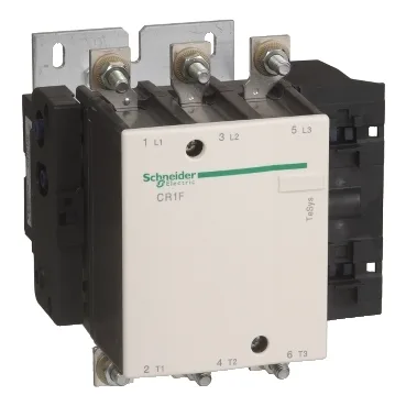
The CR1F265FZ7: The headline 265 A is the AC-4 rated operational current — that's the motor-switching duty cycle where the contactor closes onto a locked-rotor inrush and breaks the full-load current. If your application is resistive heating (AC-1) or light motor starting (AC-3), the contactor can handle higher currents: the average impedance per pole is 0.32 mOhm, and the power dissipation runs 22 W per pole in AC-3 and 39 W per pole in AC-1. The 110 V DC control voltage has a latching range of 0.85 to 1.1 Uc and an unlatching range of 0.85 to 1.1 Uc, so the coil will hold in at 93.5 V DC and drop out reliably at the same threshold. Average consumption is 500 W DC during latching and 40 W DC during unlatching — the coil only draws power during the switching transient, not continuously. The rated insulation voltage is 1000 V per IEC 60947-4 and BS 775, and 1500 V per VDE 0110 group C. The rated short-time withstand current (Icw) is 2200 A for 1, 5, and 10 seconds at 40 °C, tapering to 480 A for 10 minutes. That means it can ride through a downstream fault long enough for a backup fuse or breaker to clear — coordination study input, not a continuous rating.
The CR1F265FZ7 is a panel-mount contactor, not DIN-rail — it bolts in. The power circuit connections accept lugs, ring terminals, or bars up to 240 mm² per pole, with a bolted connection torqued to 35 N·m (309.8 lbf·in). The footprint is 8.4 in deep by 7.9 in wide by 8.0 in tall (213 x 201.5 x 203 mm). That's a substantial block — plan the gland plate and busbar routing accordingly. The associated fuse recommendation is 315 A aM or 400 A gG at ≤ 440 V, so the upstream protection should be sized to that.