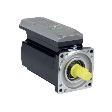
What the ILM1001P11F0000 actually is in a PacDrive 3 panel
The ILM1001P11F0000 is a Schneider Electric PacDrive 3 ILM servo motor with an integrated drive — a single mechanical unit that combines the motor, feedback device, and servo amplifier in one housing rather than a separate drive cabinet and motor cable run. The Device short name is ILM and the Product or Component Type is servo motor integrated drive, both pulled from the device record itself. That integration is the main reason the part is specified for machine builders who want to cut cabinet volume and the cabling between controller, drive, and motor. The motor delivers 600 W of nominal output power at 3000 rpm, with a nominal torque of 1.9 N·m and a continuous stall torque of 2.5 N·m when the rotor is held at zero speed. Peak stall torque reaches 9.6 N·m for short acceleration and deceleration moves — the figure a sizing engineer looks at when calculating the worst-case mechanical load during a fast index. The continuous stall current is 1.8 A and the maximum RMS current is 7.4 A, so the drive section has the headroom to deliver those peak torques without immediately tripping.
Feedback, brake, and the constants the commissioning engineer sets against
Feedback is an absolute single-turn SinCos Hiperface encoder, which gives the drive absolute position on power-up without a homing move — important on machines where the load can drift while the controller is off. The torque constant is 1.39 N·m/A measured at 120 °C winding temperature, and the back-EMF constant is 90 V/krpm at 20 °C; both numbers are what the drive uses internally to translate a current command into a torque output and a speed into a generated voltage, so they directly affect loop tuning. Stator resistance is 9.8 Ω phase-to-phase at 20 °C and stator inductance is 45.7 mH phase-to-phase at the same point — these set the electrical time constant of the motor and constrain how aggressively the current loop can be closed. The motor is supplied with a holding brake sized at 5.5 N·m, enough to hold the rotor and any vertical-axis load stationary when the servo is de-energised; this is the figure the safety circuit checks when verifying the axis will not drop on a power loss.
Mounting, thermal, and what the flange tells the panel builder
The motor flange is 100 mm with a centring collar diameter of 95 mm, mounting on an international standard flange pattern with four 9 mm holes — a common footprint that drops into a standard machine-frame cut-out. The shaft is keyed, 19 mm in diameter and 40 mm long, with no second shaft end; the maximum radial force the bearing can absorb is 900 N at 1000 rpm, dropping to 630 N at the 3000 rpm nominal speed, and the maximum axial force is capped at 0.2 × Fr. A pulley or pinion that pushes those limits is a service-life problem the bearing will surface first.