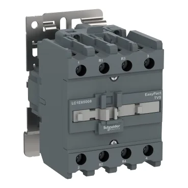
The control circuit is a wide-range AC coil at 415 V 50 Hz, with a drop-out threshold of 0.3 to 0.6 Uc and an operational range of 0.7 to 1.25 Uc across -5 to 55 °C. This gives the commissioning engineer a clear hold-in margin: the coil stays pulled in down to about 290 V and drops out reliably below about 125 V, preventing chatter on a sagging line. The contactor carries a rated insulation voltage of 690 V conforming to IEC 60947-4-1, and a rated breaking capacity of 320 A at 440 V with a making capacity of 400 A at 440 V. For the sourcing buyer, the 80 A gG associated fuse rating at ≤690 V (coordination type 1) tells you the upstream protection limit for a fault-clearing path. The 4-pole configuration is 2 NO + 2 NC, so the normally-closed poles can be used for interlocking or status feedback without adding auxiliary blocks — useful when the MRO planner needs to reduce spare-part count on a panel. Mounting is via DIN rail or plate, with a depth of 110 mm, width 85 mm, and height 127 mm.
Power circuit connections accept screw-clamp terminals: 2.5 to 25 mm² flexible with cable end, or 2.5 to 16 mm² solid. Control circuit terminals take 1 to 4 mm² flexible without cable end, or 1 to 2.5 mm² with cable end. Tightening torque is 5 N·m on the power circuit and 1.2 N·m on the control circuit — a common torque driver setting avoids overtightening on the smaller terminals. The heat dissipation of 6 to 10 W from the control circuit means the panel thermal budget should account for this when grouping multiple contactors in a sealed enclosure. Operating time is 20 to 26 ms on closing and 8 to 12 ms on opening. For the controls integrator sequencing multiple contactors, this narrow window allows predictable interlock timing without adding delay timers for basic resistive loads. The maximum operating rate of 1200 cycles per hour at 60 °C sets the upper bound for rapid cycling applications like temperature control in electric ovens.
Mechanical robustness includes vibration resistance of 1.5 Gn (contact open) and 3 Gn (contact closed) over 5 to 300 Hz, plus shock resistance of 6 Gn for 11 ms (open) and 7 Gn for 11 ms (closed). These ratings matter for the site electrical engineer specifying gear near rotating machinery or on mobile equipment skids. Fire resistance is rated at 850 °C conforming to IEC 60695-2-1, and the average impedance of the power circuit is 1.5 mOhm at Ith 60 A 50 Hz, which translates to about 5.4 W dissipation per pole under AC-1 load. The inrush power of the coil is 160 VA at 50 Hz with cos φ 0.75 — a figure the commissioning engineer needs when sizing the control transformer for a bank of contactors pulling in simultaneously.