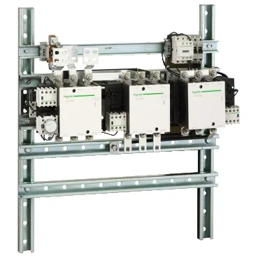
It carries a rated operational current of 400 A at ≤440 V AC for the power circuit, which translates to switching motor loads up to 375 kW at 440 V AC or 315 kW at 380/400 V AC — the AC-3 rating is the one that governs real motor starting duty, not a resistive-heater curve. The control circuit is 48 V AC at 50/60 Hz, with an operational range of 0.85...1.1 Uc and a drop-out band of 0.35...0.55 Uc. Inrush power at 20 °C is 1075 VA at 40...400 Hz, cos φ 0.9 — that inrush figure drives the control transformer sizing if you are feeding it from a panel-mounted control power supply rather than a dedicated source.
This is a plate-mounted assembly — no DIN-rail snap-on. The footprint is 725 mm wide × 276 mm deep × 180 mm tall, and the power circuit uses bolted connections with M10 bolts and bar connections accepting 30 × 5 mm busbars or ring terminals up to 150 mm². For a panel builder, that means allocating gland-plate space for the busbar entry and ensuring the enclosure depth clears the 276 mm plus cable bend radius on the power lugs. Heat dissipation is 14 W — modest for a 400 A device, but in a sealed enclosure with multiple starters that figure accumulates; derating guidance applies above 3000 m altitude.
Mechanical and electrical margins
The rated breaking capacity is 3200 A and the rated making capacity is 4000 A, both per IEC 60947-4-1; the associated fuse recommendation is 500 A gG or 400 A aM at ≤440 V. The contact structure is 3 × 3 NO power poles, with auxiliary contacts pre-configured: 1 NC + 1 NO on the KM1 star contactor, 2 NC + 1 NO on the KM2 line contactor, and 1 NC + 2 NO on the KM3 delta contactor. The mechanical interlock between the star and delta contactors is built in — no external linkage to wire.