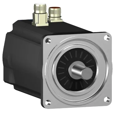
Three-phase servo with speed-torque flexibility across supply voltages
The SH31001P02A1200 is a Schneider Electric SH3 series servo motor designed for three-phase supply, delivering a nominal speed of 5000 rpm at 400 V three-phase and 6000 rpm at 480 V three-phase. Nominal torque ranges from 2.91 N.m at 115 V single-phase down to 2.27 N.m at 400 V or 480 V three-phase, so the available torque depends on the drive supply voltage — a critical factor when retrofitting into an existing cabinet with a fixed bus voltage. Continuous power is rated at 1190 W, with nominal output power reaching 1630 W at 480 V three-phase, making this motor suited for medium-duty positioning or indexing applications where sustained throughput matters.
Encoder feedback and environmental sealing for washdown duty
The absolute multiturn SinCos Hiperface encoder provides position feedback without a home cycle on power-up — the drive reads the absolute position from the encoder, which is essential for applications where the machine must resume operation immediately after a power loss. IP65 rating on the motor body and shaft bushing, with IP67 on the housing, means this motor withstands direct washdown in food-and-beverage or pharmaceutical lines — the shaft seal and housing gasket keep water out during hose-down cleaning cycles. Natural convection cooling (no external fan) means the motor relies on its own surface area and airflow from the machine motion to dissipate heat — at low speeds or in still-air enclosures, the continuous torque must be derated below the 2.94 N.m continuous stall figure.
Mechanical interface — smooth shaft, no brake, standard flange
The smooth shaft (no keyway) with a 19 mm diameter and 40 mm shaft length requires a clamping-type coupling or pulley — no key to transmit torque, so the clamping force must be verified against the peak torque of 9.6 N.m to prevent slip during acceleration. Without a holding brake, the motor cannot hold the load at standstill when power is removed — the machine design must include an external brake or a self-locking mechanism (e.g., a leadscrew with backdrive prevention) for vertical-axis or safety-hold applications. The 100 mm international standard flange (IEC/NEMA compatible) with a 95 mm centring collar and 9 mm mounting holes bolts directly to standard gearboxes or machine frames — the 3.5 mm centring collar depth ensures concentric alignment.
Electrical parameters for drive sizing and tuning
Stator resistance of 3.8 Ohm and inductance of 9.5 mH define the electrical time constant and current ripple — a drive with a switching frequency below 4 kHz may see increased ripple current and additional motor heating at low speeds. The torque constant of 0.84 N.m/A at 120°C (hot motor) and back EMF constant of 60 V/krpm at 20°C are the key parameters for the drive's current loop tuning and velocity loop gain — the drive must be configured with these values for stable operation across the speed range. Maximum continuous stall current is 3.5 A, while the peak current (3-second rating) is 12.0 A — the drive must be sized to supply 12 A for acceleration transients and 3.5 A continuously at standstill without tripping on overcurrent.
The electrical connection offers both a rotatable right-angled connector and a straight connector option — the cable exit direction can be adjusted in the field to fit tight cable-tray routing or panel entry points. Maximum radial force on the shaft is speed-dependent: 900 N at 1000 rpm, dropping to 530 N at 5000 rpm — belt-driven loads must be checked against this curve to avoid bearing overload at the operating speed.