Torque and speed curves — matching the load profile
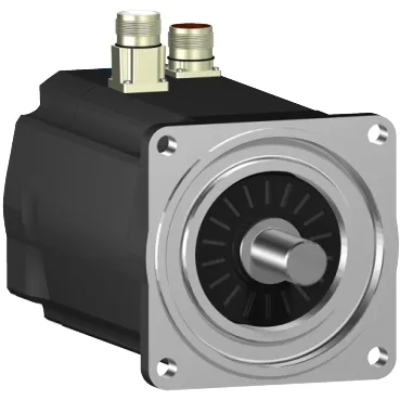
The SH31403P01F1000: This is a three-phase servo motor with nominal speeds that shift with the supply voltage: 750 rpm on 115 V single-phase, 1500 rpm on 230 V single-phase, 3000 rpm on 400 V three-phase, and 3600 rpm on 480 V three-phase. Nominal torque follows the same voltage dependency — 218.6 lbf·in (24.7 N·m) at 115 V single-phase, dropping to 80.5 lbf·in (9.1 N·m) at 480 V three-phase — so the drive voltage selection directly sets the available torque at rated speed. Continuous power is 4100 W, with nominal output power varying from 1940 W at 115 V single-phase up to 4050 W at 400 V three-phase. Peak stall torque reaches 798.3 lbf·in (90.2 N·m) across the 115–480 V three-phase range, giving a 3.2× torque overload margin above the continuous stall torque of 246.05 lbf·in (27.8 N·m).
The integrated holding brake delivers 318.6 lbf·in (36 N·m) of holding torque — this is the static torque that keeps the load position when the drive is disabled, not a dynamic braking torque for deceleration. The absolute single-turn SinCos Hiperface encoder provides position feedback at power-up without a homing cycle, which matters for applications where the machine must resume operation after a power loss without referencing. Maximum mechanical speed is 4000 rpm, so the encoder and bearings are rated for overspeed margin above the 3600 rpm nominal at 480 V.
Mounting and mechanical interface — flange, shaft, and force limits
The motor mounts to an international standard flange with a 5.5 in (140 mm) flange size and a 5.1 in (130 mm) centring collar, matching the common B5 / IM B5 flange pattern for direct coupling to gearboxes or pulleys. The smooth shaft has a 0.9 in (24 mm) diameter and 2.0 in (50 mm) length, so the coupling or pulley bore must be machined for a keyless interference fit or a clamping bushing. Maximum radial force is 2420 N at 1000 rpm, derating to 1670 N at 3000 rpm — this sets the belt tension or overhung load limit and is a common failure mode if exceeded at higher speeds. Maximum axial force is 300 N; any thrust load from helical gears or fan impellers must stay below this to avoid bearing preload damage.
Thermal and electrical parameters — sizing the drive and cooling
Cooling is by natural convection only — no integrated fan, so the motor relies on the machine frame or ambient airflow for heat rejection, and the continuous torque rating assumes free air circulation around the housing. Continuous stall current is 17.6 A, with a maximum RMS current of 61 A — the drive must be sized to supply the peak current during acceleration without saturating its current loop. Stator resistance is 0.4 Ω and stator inductance is 7.72 mH, giving an electrical time constant of about 19 ms — relevant for the drive's current regulator tuning and for estimating I²R losses at stall.
Environmental protection and connection
IP54 protection at the shaft bushing without the shaft seal ring, and IP65 on the motor body and with the shaft bushing seal ring installed — the difference is whether the shaft exit is sealed against low-pressure water jets. The electrical connection uses a straight connector, so the cable exits axially from the motor body — account for this in the cable routing and bend radius when mounting in a confined space.