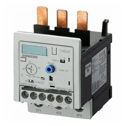
The Siemens SIRIUS 3RB2036-2QW1 is a 3-pole solid-state overload relay designed to protect motors against overload and phase failure. Its CLASS 20E trip class means it will trip within 20 seconds at 7.2× the set current, a standard match for general-purpose induction motors driving pumps, fans, and conveyors — not for high-inertia loads that need a longer 30E class. It carries ATEX Ex II (2) GD certification for gas and dust hazardous areas. The substance prohibition date is 07/01/2006. The relay operates with straight-through transformers for the main current circuit, meaning the motor power cables pass directly through the relay housing without looping. This keeps the wiring compact and reduces the chance of a loose connection at the transformer terminals.
The auxiliary contact block provides one normally-closed (NC) contact and no normally-open (CO) contacts. That single NC is typically wired into the motor contactor's control circuit as a safety chain break — if the relay trips, the NC opens and drops out the contactor. With no NO spare, you cannot also signal a trip to a PLC without adding an external interface relay. Switching capacity varies with voltage: 2 A at 24 V, 4 A at 120 V, 3 A at 230 V. At higher control voltages like 220 V it drops to 0.11 A, so verify your pilot duty load matches the curve at your actual control voltage — particularly if driving multiple contactors in parallel. Surge voltage withstand is rated at 6 kV, and burst immunity meets IEC 61000-4-4 severity level 3 (2 kV on power ports, 1 kV on signal ports). In a panel with VFDs or contactor switching nearby, that level of transient immunity means the relay is unlikely to nuisance-trip from conducted EMI on the control wiring. Shock resistance is 15g for 11 ms, so it can be mounted on a panel door or a machine frame that sees occasional impact — not a high-vibration crusher or press, but typical industrial machinery. Power dissipation is just 0.02 W per pole, so the relay adds negligible heat to the enclosure. No derating calculation needed for this component in a sealed box.
Mounting is stand-alone — no DIN-rail clip, no snap-on. The relay is fastened directly to a mounting plate with screws. It can be installed in any orientation, which helps when fitting into a crowded panel where vertical or horizontal clearance is tight. Dimensions: 55 mm wide, 92 mm tall, and 109 mm deep. Depth determines enclosure clearance. Clearance distances: 0 mm upwards, forwards, backwards, and downwards — meaning it can be butted directly against other components or the enclosure wall on those sides. Side clearance needs 6 mm, so plan for that gap between adjacent devices. Screw-type terminals accept solid conductors from 0.5 to 4 mm² on the main circuit, and 0.5 to 2.5 mm² for auxiliary wiring. Two conductors of the same size can be terminated per clamp, useful for daisy-chaining control power.
Relative humidity during operation can reach 100 %, so condensation inside the enclosure is not a problem for the relay itself — but the screw terminals should be torqued to spec to avoid corrosion in persistently wet environments. The substance prohibition date of 07/01/2006 aligns with the original EU RoHS directive (RoHS 1). The relay is RoHS-compliant for that standard; if RoHS 3 (2011/65/EU + 2015/863) compliance documentation is needed for your quality file, request the manufacturer's declaration of conformity with the order.