End-of-life — what it means for the BOM line
The 3RG9001-0AC00: Sourcing runs through independent surplus and broker channels. Quantities are lot-specific and confirmed at RFQ — no factory lead time applies.
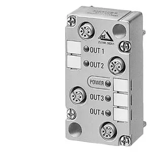
This is the user module only — 2 inputs / 2 relay outputs in an IP67 housing (27 mm × 45 mm × 90 mm). It mounts to a standard rail or wall via the FK or Pg coupling module (sold separately). The four M12 sockets are on the module face: D0 and D1 for inputs, D2 and D3 for outputs. The relay outputs need an external 20–30 V DC auxiliary supply (PELV per VDE 0106, protection class III) fed through the M12 connector. Without that supply the output circuits have no power — the module reads inputs and communicates on the AS-Interface bus, but the relays won't switch.
Relay output ratings — the so-what for the load
Each relay output is rated 1 A at 12 V DC (DC-12) and 0.5 A at 24 V DC (DC-13). The aggregate output current across both channels is 2 A. Built-in short-circuit and induction protection means the module handles the flyback from the relay coil without an external diode. On a communication failure the relay outputs hold their last state — no drop-out, no unintended restart.
Input side — PNP, 10 V threshold
The two digital inputs are PNP (sourcing), switching level high at ≥10 V, low at ≤1.5 mA. Minimum signal current is 5 mA — enough to drive a standard 3-wire proximity sensor without a pull-up resistor. Input voltage range is 20–30 V DC, matching the AS-Interface bus supply. The module draws up to 140 mA from the AS-Interface bus for its own electronics; the output power comes from the separate auxiliary supply, not the bus.