Contact configuration and what it means for your control circuit
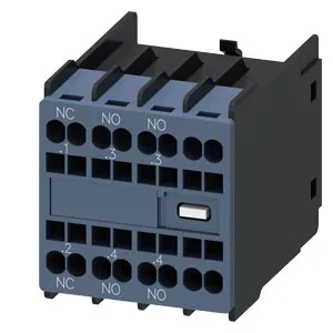
The 3RH2911-2HA21: This auxiliary switch block mounts on the front of Siemens 3RT2 contactors and 3RH2 contactor relays, adding 2 normally-open and 1 normally-closed auxiliary contacts to the switching device. The contact arrangement is 1 NC + 1 NO + 1 NO across three current paths, giving you one break-before-make pair and one independent make contact — enough to interlock a reversing starter or signal a PLC input while the main power path stays separate.
Rated currents across the voltage range — the AC-15 duty curve
The maximum thermal current is 10 A, but the switching capacity depends on the operating voltage and load type. At 24 V AC-15 (solenoid/contactor coil duty) the contacts are rated 10 A; at 110 V the rating drops to 3 A, and at 220 V it falls to 1.2 A. For DC switching the derating is steeper: 6 A at 24 V DC, 2 A at 60 V, 1 A at 110 V, and 0.3 A at 220 V. The DC arc extinguishes slower than AC, so the contact gap and material limit the interrupting capacity — this matters when the auxiliary switch controls a DC brake coil or a DC-powered indicator. At 690 V AC-15 the rated current is 1 A, and the rated insulation voltage is 690 V with pollution degree 3 — the contacts can live on a 480/277 V panel bus without derating for altitude or contamination.
Termination and mounting — spring-loaded terminals on a snap-on footprint
The auxiliary and control circuit connections use spring-loaded terminals — no screw torque to verify, no periodic re-torquing on a vibrating panel. Each terminal accepts two conductors: 0.5 to 1.5 mm² with ferrule, or 0.5 to 2.5 mm² without ferrule (20 to 14 AWG). Mounting is snap-on DIN rail (35 mm). The block is 36 mm wide, 47.7 mm deep, and 41.5 mm tall — it adds about 36 mm to the width of the base contactor or relay, so plan the DIN rail layout accordingly.
Lifecycle and sourcing — current production, quoted to order
It is part of the Siemens SIRIUS family, which is an active product portfolio with broad installed base.
Contact reliability and mechanical endurance
The mechanical service life is 10 million switching cycles typical — the spring-loaded terminal block and the snap-on latch will outlast most panel rebuild cycles. Contact reliability is specified at 1 faulty switching per 100 million operations at 17 V, 1 mA, which covers dry-circuit PLC input signals where oxide films on silver contacts can cause intermittent opens. Surge voltage resistance is 6 kV, and the operating temperature range is -25 to +60 °C with storage from -55 to +80 °C — suitable for unheated electrical rooms and outdoor-rated enclosures within the IP20 front protection limit.