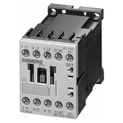
Siemens 3RT1017-2BB42 — Contactors

Siemens 3RT1017-2BB42 SIRIUS Power Contactor, 24 VDC Coil, S

MPN3RT1017-2BB42

Siemens SIRIUS power contactor, size S00, 24 VDC coil, spring-loaded terminals for main and auxiliary circuits, rated 5.5 kW at 400 V AC-2.

Source DocumentedChannel stated on listing & quote
Condition PhotosReal unit photos / video on request
WhatsApp AnswersFast human replies for machine-down parts
Worldwide DispatchDHL/FedEx — transit quoted per order
Independent China distributor & sourcing agent· Listing updated Sep 2026

Specifications

3RT1017-2BB42 — Identification
ParameterValue
Contactor frame sizeS00
3RT1017-2BB42 — Ratings & Performance
ParameterValue
Rated operational current, AC-12, max.10 A
Rated operational current, AC-4 @ 400 V8.5 A
Rated value @ 400 V3 A
Rated value @ 500 V5.5 kW
Rated value @ 690 V5.5 kW
Rated value @ 230 V6 A
Rated value @ 24 V10 A
Rated value @ 60 V2 A
Rated value @ 110 V1 A
Rated value @ 220 V0.3 A
3RT1017-2BB42 — Control & Coil
ParameterValue
Control supply voltage typeDC
3RT1017-2BB42 — Contacts & Poles
ParameterValue
Main poles3
Main NO contacts3
Auxiliary contact reliability1 faulty switching per 100 million (17 V, 1 mA)
3RT1017-2BB42 — Protection & Coordination
ParameterValue
Short-circuit coordination type 1, fusefuse gL/gG: 35 A
Short-circuit coordination type 2, fusefuse gL/gG: 20 A
Aux. switch short-circuit protection, fusefuse gL/gG: 10 A
3RT1017-2BB42 — Connection & Mounting
ParameterValue
Main circuit connectionspring-loaded terminals
Aux. / control circuit connectionspring-loaded terminals
Conductor cross-section, solid2x (0.25 ... 2.5 mm²)
Conductor cross-section, solid or stranded2x (0,25 ... 2,5 mm²)
Conductor cross-section, finely stranded w/ ferrule2x (0.25 ... 1.5 mm²)
Mounting methodscrew and snap-on mounting onto 35 mm standard mounting rail according to DIN EN 50022
Side-by-side mountingYes
3RT1017-2BB42 — Durability
ParameterValue
Durability (operating cycles, typ.)30 000 000
Durability with aux. switch block (cycles, typ.)10 000 000
3RT1017-2BB42 — Environmental
ParameterValue
Installation altitude, max.2 000 m
3RT1017-2BB42 — Mechanical
ParameterValue
Width45 mm
Height60 mm
Depth73 mm

Product details

The 24 VDC coil draws 3.3 W during both closing and holding, which is a steady-state load you can budget for in your 24 VDC supply — no inrush spike to size around. Spring-loaded terminals on both the main and auxiliary/control circuits accept 2x (0.25 to 2.5 mm²) solid or stranded wire, or 2x (24 to 14 AWG). That means no screw torque checks during commissioning — strip, insert, and the cage holds.

In AC-4 duty (plugging, inching, reversing), the rated operational current is 8.5 A at 400 V. That's the figure to use for frequent jogging or reversing applications — the AC-3 or AC-1 numbers aren't the limiting factor here. For type of coordination 2 (short-circuit protection with minimal damage to the contactor), Siemens specifies a gL/gG fuse of 20 A. For type 1 coordination (contactor replacement after fault), a 35 A fuse is allowed. This guides your upstream protective device selection.

That suits most industrial control cabinets without derating for typical factory floor conditions. IP20 on the front and at the terminals — finger-safe but not washdown-rated. Mount inside an enclosure if the environment sees dust or moisture.

Frequently asked questions

What are the key ratings for motor switching?

Rated 5.5 kW at 400 V AC-2, 5.5 kW at 500 V and 690 V, and 8.5 A at 400 V AC-4. The coil is 24 VDC, drawing 3.3 W steady-state.

What wire sizes does the spring-loaded terminal accept?

It accepts 2x (0.25 to 2.5 mm²) solid or stranded, or 2x (24 to 14 AWG) for both main and auxiliary circuits.

What is the mounting method?

Screw and snap-on mounting onto a 35 mm standard mounting rail per DIN EN 50022. Side-by-side mounting is supported.

What short-circuit protection is required?

For type of coordination 2, use a gL/gG fuse rated 20 A. For type 1 coordination, a 35 A gL/gG fuse is specified.

MPN
3RT1017-2BB42