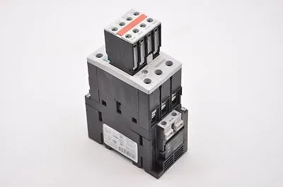
Siemens 3RT1025-1BB44 — Contactors

Siemens 3RT1025-1BB44 SIRIUS Power Contactor, 24 VDC Coil, S

MPN3RT1025-1BB44

Siemens SIRIUS 3RT1025-1BB44 power contactor, S0 frame, 24 VDC coil, screw-type terminals, DIN rail mount, IP20 front.

$91.44Ref. price · indicative, final on quote
Sourced new & surplus through independent channelsAuthenticity-screened · ESD-safe packingListing updated Jul 2026

Specifications

3RT1025-1BB44 — Identification
ParameterValue
Contactor frame sizeS0
3RT1025-1BB44 — Ratings & Performance
ParameterValue
Rated operational current, AC-12, max.10 A
Rated operational current, AC-4 @ 400 V15.5 A
Rated value @ 400 V3 A
Rated value @ 500 V10 kW
Rated value @ 690 V11 kW
Rated value @ 230 V6 A
Rated value @ 24 V10 A
Rated value @ 60 V2 A
Rated value @ 110 V1 A
Rated value @ 220 V0.3 A
3RT1025-1BB44 — Control & Coil
ParameterValue
Control supply voltage typeDC
3RT1025-1BB44 — Contacts & Poles
ParameterValue
Main poles3
Main NO contacts3
Auxiliary contact reliability1 faulty switching per 100 million (17 V, 1 mA)
3RT1025-1BB44 — Protection & Coordination
ParameterValue
Short-circuit coordination type 1, fusefuse gL/gG: 63 A
Short-circuit coordination type 2, fusefuse gL/gG: 25 A
Aux. switch short-circuit protection, fusefuse gL/gG: 10 A
3RT1025-1BB44 — Connection & Mounting
ParameterValue
Main circuit connectionscrew-type terminals
Aux. / control circuit connectionscrew-type terminals
Conductor cross-section, solid2x (0.5 ... 1.5 mm²), 2x (0.75 ... 2.5 mm²), max. 2x (0.75 ... 4 mm²)
Conductor cross-section, solid or stranded2x (1 ... 2,5 mm²), 2x (2,5 ... 6 mm²), max. 2x 10 mm²
Conductor cross-section, finely stranded w/ ferrule2x (0.5 ... 1.5 mm²), 2x (0.75 ... 2.5 mm²)
Mounting methodscrew and snap-on mounting onto 35 mm standard mounting rail according to DIN EN 50022
Side-by-side mountingYes
3RT1025-1BB44 — Durability
ParameterValue
Durability (operating cycles, typ.)10 000 000
Durability with aux. switch block (cycles, typ.)10 000 000
3RT1025-1BB44 — Environmental
ParameterValue
Operating temperature range-25 ... +60 °C
Installation altitude, max.2 000 m
3RT1025-1BB44 — Mechanical
ParameterValue
Width45 mm
Height85 mm
Depth150 mm

Product details

That means you can pull the old unit off the rail, land the wires on the same terminals with a screwdriver, and be back in business — no crimping ferrules needed unless your site standard calls for them. The terminal area itself is IP00 — that's typical for contactors; the enclosure provides the real ingress protection.

Coil and contact ratings — the numbers that decide fit

Coil is a 24 VDC pickup, pulling 5.4 W during both closing and holding. Holding power equals inrush. On the main contacts, the AC-3 motor-switching rating at 400 V is 7.5 kW — that is the number most buyers care about for a standard three-phase induction motor. The AC-4 reversing or plugging rating at 400 V is 15.5 A, lower than the AC-3 rating because of the higher switching stress. For resistive loads (AC-1), the maximum operational current is 10 A at 400 V. The contactor also carries ratings at other voltages: at 230 V it switches 6 A, at 500 V it switches 10 kW, and at 690 V it switches 11 kW. These are for the main circuit under the respective duty classes — match the voltage on your line. Auxiliary contact ratings are given for the DC switching side: 10 A at 24 V, 2 A at 60 V, 1 A at 110 V, and 0.3 A at 220 V. That is important if you are using the aux contacts to switch a PLC input or a smaller relay coil — the DC rating drops fast as voltage rises.

Installation constraints and wiring details

The S0 frame measures 45 mm wide by 85 mm tall by 150 mm deep. Main circuit terminals accept solid or stranded wire: 2x (1... 2.5 mm²), 2x (2.5... 6 mm²), or a single up to 10 mm². Auxiliary circuit terminals take 2x (0.5... 1.5 mm²), 2x (0.75... 2.5 mm²), or a single up to 4 mm². AWG equivalents are also listed: main terminals take 2x (16... 12), 2x (14... 10), or 1x 8 AWG; aux terminals take 2x (20... 16), 2x (18... 14), or 1x 12 AWG.

Short-circuit protection coordination

These are the values to hand to the panel builder when sizing the branch circuit protection.

Mechanical life and compliance

The typical mechanical endurance is 10 million operations — that is the unloaded mechanical life. Electrical life will be lower and depends on the switching current and voltage; the 10 million figure is a reference for how many times the armature can cycle before mechanical wear becomes a concern. The product carries a substance prohibition date of 01.07.2006, which aligns with the original EU RoHS directive (RoHS 1). This means the contactor is RoHS-compliant for the six original restricted substances.

Frequently asked questions

What is the depth of the 3RT1025-1BB44?

The depth is 150 mm. That is the dimension from the DIN rail mounting surface to the farthest forward point — important for enclosure depth clearance.

What wire sizes can I terminate on the 3RT1025-1BB44?

Main circuit terminals accept 2x (1... 2.5 mm²), 2x (2.5... 6 mm²), or max. 1x 10 mm² solid/stranded. Auxiliary circuit terminals accept 2x (0.5... 1.5 mm²), 2x (0.75... 2.5 mm²), or max. 1x 4 mm². AWG equivalents: main 2x (16-12), 2x (14-10), 1x 8; aux 2x (20-16), 2x (18-14), 1x 12.

MPN
3RT1025-1BB44