The 45 mm wide, 85 mm high, 101 mm deep footprint fits standard S0 contactor spacing on DIN rail. Main circuit screw terminals accept 2x (1…2.5 mm²) solid/stranded or 2x (2.5…6 mm²) stranded, up to 1x 10 mm². Auxiliary terminals take 2x (0.5…1.5 mm²) solid/stranded or 2x (0.75…2.5 mm²), max 2x (0.75…4 mm²). For AWG, main contacts accept 2x (16…12), 2x (14…10), 1x 8; auxiliary accept 2x (20…16), 2x (18…14), 1x 12. Rated operational current AC-12 maximum is 10 A. Side-by-side mounting is permitted; no additional spacing required. For type 2 coordination, use gL/gG fuse 25 A; type 1 coordination allows 63 A.
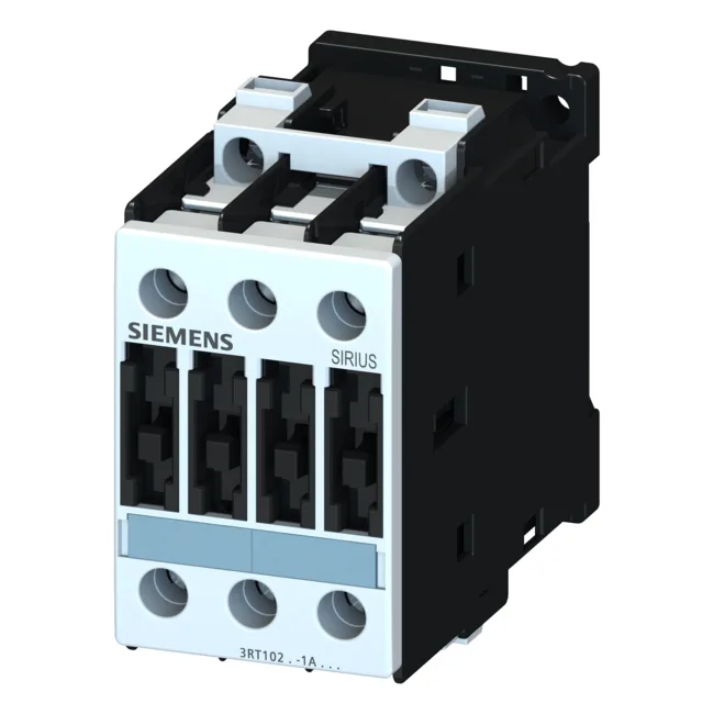
Siemens 3RT1025-1BB40 Power Contactor, 24 V DC, S0
MPN3RT1025-1BB40
Siemens SIRIUS 3RT1025-1BB40 power contactor, size S0, 24 V DC coil, 45 mm width, 101 mm depth, IP20 front, screw terminals.
$119.00 – $145.00Ref. price · indicative, final on quote
Source DocumentedChannel stated on listing & quote
Condition PhotosReal unit photos / video on request
WhatsApp AnswersFast human replies for machine-down parts
Worldwide DispatchDHL/FedEx — transit quoted per order
Independent China distributor & sourcing agent· Listing updated Sep 2026
Specifications
| Parameter | Value |
|---|---|
| Contactor frame size | S0 |
| Parameter | Value |
|---|---|
| Rated operational current, AC-12, max. | 10 A |
| Rated operational current, AC-4 @ 400 V | 15.5 A |
| Rated value @ 400 V | 3 A |
| Rated value @ 500 V | 10 kW |
| Rated value @ 690 V | 11 kW |
| Rated value @ 230 V | 6 A |
| Rated value @ 24 V | 10 A |
| Rated value @ 60 V | 2 A |
| Rated value @ 110 V | 1 A |
| Rated value @ 220 V | 0.3 A |
| Parameter | Value |
|---|---|
| Control supply voltage type | DC |
| Parameter | Value |
|---|---|
| Main poles | 3 |
| Main NO contacts | 3 |
| Auxiliary contact reliability | 1 faulty switching per 100 million (17 V, 1 mA) |
| Parameter | Value |
|---|---|
| Short-circuit coordination type 1, fuse | fuse gL/gG: 63 A |
| Short-circuit coordination type 2, fuse | fuse gL/gG: 25 A |
| Aux. switch short-circuit protection, fuse | fuse gL/gG: 10 A |
| Parameter | Value |
|---|---|
| Main circuit connection | screw-type terminals |
| Aux. / control circuit connection | screw-type terminals |
| Conductor cross-section, solid | 2x (0.5 ... 1.5 mm²), 2x (0.75 ... 2.5 mm²), max. 2x (0.75 ... 4 mm²) |
| Conductor cross-section, solid or stranded | 2x (1 ... 2,5 mm²), 2x (2,5 ... 6 mm²), max. 2x 10 mm² |
| Conductor cross-section, finely stranded w/ ferrule | 2x (0.5 ... 1.5 mm²), 2x (0.75 ... 2.5 mm²) |
| Mounting method | screw and snap-on mounting onto 35 mm standard mounting rail according to DIN EN 50022 |
| Side-by-side mounting | Yes |
| Parameter | Value |
|---|---|
| Durability (operating cycles, typ.) | 10 000 000 |
| Durability with aux. switch block (cycles, typ.) | 10 000 000 |
| Parameter | Value |
|---|---|
| Operating temperature range | -25 ... +60 °C |
| Installation altitude, max. | 2 000 m |
| Parameter | Value |
|---|---|
| Width | 45 mm |
| Height | 85 mm |
| Depth | 101 mm |
Product details
Frequently asked questions
What wire sizes does the 3RT1025-1BB40 accept?
Main circuit terminals: 2x (1…2.5 mm²) solid/stranded, 2x (2.5…6 mm²) stranded, max 1x 10 mm². Auxiliary terminals: 2x (0.5…1.5 mm²) solid/stranded, 2x (0.75…2.5 mm²), max 2x (0.75…4 mm²). AWG equivalents: main 2x (16…12), 2x (14…10), 1x 8; auxiliary 2x (20…16), 2x (18…14), 1x 12.
What is the rated motor switching capacity at 400 V?
AC-2 duty: 7.5 kW; AC-4 duty: 15.5 A. This covers normal start/run and reversing or jogging applications.
MPN
3RT1025-1BB40