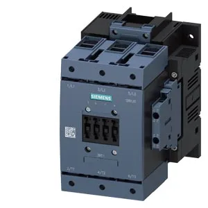
Siemens 3RT1054-1AT36 — Contactors

Siemens 3RT1054-1AT36 SIRIUS Power Contactor, S6 Frame, AC C

MPN3RT1054-1AT36
Active

Siemens SIRIUS power contactor, size S6, AC coil 3RT1054-1AT36, 170 x 120 x 172 mm, screw fixing, 16–70 mm² power wiring.

Sourced new & surplus through independent channelsAuthenticity-screened · ESD-safe packingListing updated Aug 2026

Specifications

3RT1054-1AT36 — Identification
ParameterValue
Contactor frame sizeS6
3RT1054-1AT36 — Ratings & Performance
ParameterValue
Rated operational current, AC-12, max.10 A
Rated operational current, AC-4 @ 400 V97 A
Rated value @ 400 V3 A
Rated value @ 500 V2 A
Rated value @ 690 V1 A
Rated value @ 230 V25 hp
Rated value @ 24 V10 A
Rated value @ 60 V2 A
Rated value @ 110 V1 A
Rated value @ 220 V0.3 A
3RT1054-1AT36 — Control & Coil
ParameterValue
Control supply voltage typeAC/DC
Rated value @ 50 Hz0.8
Rated value @ 50 Hz575 ... 600 V
3RT1054-1AT36 — Contacts & Poles
ParameterValue
Main poles3
Main NO contacts3
Auxiliary contact reliability1 faulty switching per 100 million (17 V, 1 mA)
3RT1054-1AT36 — Protection & Coordination
ParameterValue
Short-circuit coordination type 1, fusegG: 355 A (690 V, 100 kA)
Short-circuit coordination type 2, fusegG: 250 A (690 V, 100 kA), aM: 200 A (690 V, 50 kA), BS88: 250 A (415 V, 50 kA)
Aux. switch short-circuit protection, fusegG: 10 A (500 V, 1 kA)
3RT1054-1AT36 — Connection & Mounting
ParameterValue
Main circuit connectionbox terminal
Aux. / control circuit connectionscrew-type terminals
Conductor cross-section, solid2x (0.5 ... 1.5 mm²), 2x (0.75 ... 2.5 mm²), max. 2x (0.75 ... 4 mm²)
Conductor cross-section, solid or stranded2x (0,5 ... 1,5 mm²), 2x (0,75 ... 2,5 mm²), max. 2x (0,75 ... 4 mm²)
Conductor cross-section, finely stranded w/ ferrule2x (0.5 ... 1.5 mm²), 2x (0.75 ... 2.5 mm²)
Mounting methodscrew fixing
Side-by-side mountingYes
3RT1054-1AT36 — Durability
ParameterValue
Durability (operating cycles, typ.)10 000 000
Durability with aux. switch block (cycles, typ.)10 000 000
3RT1054-1AT36 — Environmental
ParameterValue
Operating temperature range-25 ... +60 °C
Storage temperature range-55 ... +80 °C
Installation altitude, max.2 000 m
3RT1054-1AT36 — Mechanical
ParameterValue
Width120 mm
Height172 mm
Depth170 mm
3RT1054-1AT36 — Specifications
ParameterValue
At AC40 ... 60 ms

Product details

Power wiring accepts stranded conductors from 16 to 70 mm². The auxiliary circuit uses screw-type terminals accepting 2x 0.5–1.5 mm² solid or 2x 0.75–2.5 mm² stranded, max 2x 4 mm².

Duty-cycle capability — the rating that governs real use

Maximum switching frequency: 800 operations/hour in AC-1, 400 in AC-2, 1,000 in AC-3, 130 in AC-4. AC-3e rating also at 1,000 ops/h. Arcing time runs 10–15 ms; total opening time (including arc extinction) is 40–60 ms for both AC and DC coils.

Auxiliary contact capacity

Built-in auxiliary switch rated for 10 A at 24 V, 2 A at 48/60 V, 1 A at 110 V, 0.9 A at 125 V, and 0.3 A at 220 V. These are the continuous current limits for the auxiliary contacts feeding PLC inputs, indicator lamps, or interlocking relays.

Environmental and clearance

These are the free-air spacing requirements for heat dissipation and arc flash — a panel layout that crowds the contactor below these distances will derate the switching capacity.

Frequently asked questions

What are the overall dimensions of 3RT1054-1AT36?

Depth 170 mm, width 120 mm, height 172 mm. These are the envelope dimensions for panel layout and enclosure sizing.

What wire sizes does 3RT1054-1AT36 accept on the power and auxiliary terminals?

Power terminals accept stranded conductors 16–70 mm². Auxiliary screw terminals accept 2x 0.5–1.5 mm² solid or 2x 0.75–2.5 mm² stranded, up to 2x 4 mm² maximum.

MPN
3RT1054-1AT36