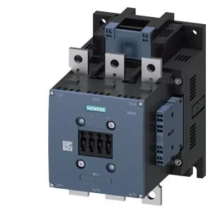
Siemens 3RT1064-2AF36 — Contactors

Siemens 3RT1064-2AF36 SIRIUS Power Contactor, S10 Size, 110-

MPN3RT1064-2AF36
Active

Siemens SIRIUS, power contactor, size S10, 3RT1064-2AF36, 110... 127 V AC/DC coil, spring-type terminals, screw fixing, 210 x 145 x 202 mm (H x W x D).

Sourced new & surplus through independent channelsAuthenticity-screened · ESD-safe packingListing updated Aug 2026

Specifications

3RT1064-2AF36 — Identification
ParameterValue
Contactor frame sizeS10
3RT1064-2AF36 — Ratings & Performance
ParameterValue
Rated operational current, AC-12, max.10 A
Rated operational current, AC-4 @ 400 V195 A
Rated value @ 400 V3 A
Rated value @ 500 V2 A
Rated value @ 690 V1 A
Rated value @ 230 V6 A
Rated value @ 24 V10 A
Rated value @ 60 V2 A
Rated value @ 110 V1 A
Rated value @ 220 V0.3 A
3RT1064-2AF36 — Control & Coil
ParameterValue
Control supply voltage typeAC/DC
Rated value @ 50 Hz0.9
Rated value @ 50 Hz110 ... 127 V
3RT1064-2AF36 — Contacts & Poles
ParameterValue
Main poles3
Main NO contacts3
Auxiliary contact reliability1 faulty switching per 100 million (17 V, 1 mA)
3RT1064-2AF36 — Protection & Coordination
ParameterValue
Short-circuit coordination type 1, fusegG: 500 A (690 V, 100 kA)
Short-circuit coordination type 2, fusegG: 400 A (690 V, 100 kA), aM: 315 A (690 V, 50 kA), BS88: 400 A (415 V, 50 kA)
Aux. switch short-circuit protection, fusegG: 10 A (500 V, 1 kA)
3RT1064-2AF36 — Connection & Mounting
ParameterValue
Main circuit connectionConnection bar
Aux. / control circuit connectionspring-loaded terminals
Conductor cross-section, solid2x (0.25 ... 2.5 mm²)
Conductor cross-section, solid or stranded2x (0,25 ... 2,5 mm²)
Conductor cross-section, finely stranded w/ ferrule2x (0.25 ... 1.5 mm²)
Mounting methodscrew fixing
Side-by-side mountingYes
3RT1064-2AF36 — Durability
ParameterValue
Durability (operating cycles, typ.)10 000 000
Durability with aux. switch block (cycles, typ.)10 000 000
3RT1064-2AF36 — Environmental
ParameterValue
Operating temperature range-25 ... +60 °C
Storage temperature range-55 ... +80 °C
Installation altitude, max.2 000 m
3RT1064-2AF36 — Mechanical
ParameterValue
Width145 mm
Height210 mm
Depth202 mm
3RT1064-2AF36 — Specifications
ParameterValue
At AC40 ... 80 ms

Product details

Siemens SIRIUS 3RT1064-2AF36 — S10 Power Contactor, 110–127 V Coil

It carries a 110... 127 V rated coil voltage, with a pickup threshold of 0.8 times the rated value — meaning the coil must see at least 88 V at the 110 V end of the range to pull in reliably. Coil termination uses spring-type terminals, which speeds wiring and holds up better under vibration than screw-clamp alternatives on the control side. Mounting is by screw fixing onto a vertical surface, with the contactor body rotatable ±90° and tiltable ±22.5° front-to-back. This gives panel builders flexibility in orientation without derating, as long as the mounting surface remains vertical.

Switching Duty and Mechanical Endurance

The 3RT1064-2AF36 is rated for different maximum switching frequencies depending on the utilization category. In AC-1 (resistive loads) it can manage up to 750 operations per hour. For AC-3 (squirrel-cage motor starting, switching off during running) the limit is 500 ops/h, and the same figure applies for AC-3e (enhanced AC-3). AC-2 (slip-ring motor starting) drops to 250 ops/h, and AC-4 (plugging, inching, reversing) is the most demanding at 130 ops/h. These are maximum mechanical rates; the thermal load of the connected circuit may further limit the practical duty cycle. The arcing time across the main contacts is 10... 15 ms. Operating times for both AC and DC coil supplies are identical at 40... 80 ms — no speed difference between supply types, which simplifies timing coordination in mixed-control panels.

Auxiliary Contact Ratings and Conductor Sizing

An auxiliary switch is integrated. Its contact ratings are specified by voltage: 10 A at 24 V, 2 A at 48 V, 2 A at 60 V, and 1 A at 110 V. These are the maximum continuous currents the auxiliary contacts can break at the respective voltage levels — useful for sizing the control transformer and verifying the pilot devices in the interlock chain. Main power conductors accept stranded wire from 70 up to 240 mm² — sized for the full rated current of the S10 frame. Auxiliary (coil and signal) terminals accept solid or stranded conductors of 2x (0.25... 2.5 mm²), or 2x (0.25... 2.5 mm²) for the same gauge range depending on the entry. This covers standard control wiring up to 14 AWG, with room for daisy-chaining two conductors per terminal.

Environmental Limits and Lifecycle Status

The power factor at rated load is 0.9 at both 50 Hz and 60 Hz, and the full-scale overload factor is 1.1.

Frequently asked questions

What are the key dimensions and mounting requirements for the 3RT1064-2AF36?

The contactor measures 210 mm high by 145 mm wide by 202 mm deep. It mounts by screw fixing onto a vertical surface, with the body rotatable ±90° and tiltable ±22.5° front-to-back. Minimum clearance distances are 10 mm upwards, 10 mm downwards, 20 mm forwards, and 10 mm at the side.

What coil voltage does the 3RT1064-2AF36 require?

The coil is rated for 110... 127 V AC/DC. The pickup threshold is 0.8 times the rated value, so the coil must see at least 88 V at the 110 V end of the range to pull in reliably. Coil connections use spring-type terminals.

How do I get current pricing and availability for the 3RT1064-2AF36?

The part is sourced and quoted to order against an RFQ through independent distribution channels. Current pricing and availability are confirmed at the time of quotation — submit an RFQ for a firm quote and lead time.

MPN
3RT1064-2AF36