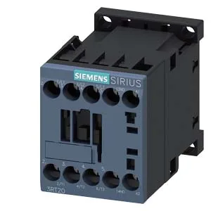
The 3RT2017-2LB42-1AA0: The 24 V DC coil with spring-type terminals means no screwdriver for the control wiring — strip, push, done. That saves a few minutes per termination on a multi-contactor panel, and spring cages hold better under vibration than screw clamps on a 45 mm wide footprint.
What the DC switching ratings mean for fit
DC arc extinction is the hard part for a contactor, and the datasheet makes it clear: at 24 V rated value it handles 10 A, at 48 V it drops to 2 A, at 125 V it's 0.9 A, and at 230 V it's 0.3 A. If your BOM calls for switching a 48 V DC solenoid bank pulling 1.5 A, this part fits; if the solenoid pulls 3 A, the 2 A limit says no — you need a larger frame or a DC-rated power contactor. The AC-3 motor rating at 400 V is 3 A, and at 230 V it carries 2 hp. That's a small motor — fractional-horsepower pump or a small conveyor section. For a 7.5 kW drive input contactor, this is undersized; for a pilot-duty or coupling application between PLC output and a larger contactor coil, it's right-sized.
Mechanical endurance and switching frequency
Rated at 30,000,000 mechanical operations typical, this contactor will outlast the panel it's in for most cyclic applications. The switching-frequency limits tell the real story: at AC-1 (resistive) you can hammer it at 1,000 cycles per hour, at AC-3 (motor) it's 750 per hour, and at AC-4 (plugging/inching) it's 250 per hour. If your machine cycles a coupling contactor every 3 seconds, the AC-1 limit says fine; if it's reversing a motor every 10 seconds, the AC-4 limit says you'll exceed the rated frequency and should step up to a larger contactor or reduce the duty.
Panel integration and clearances
The 45 mm width is one standard module — you can stack several in a row. That's tight enough for a crowded panel, but the 10 mm forward clearance means you can't butt a gland plate right against the front of the contactor — leave room for the arcing space (arcing time 10 to 15 ms) and for the spring-cage tool access.