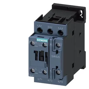
The contactor is rated for 1 000 switching cycles per hour under AC-1, AC-2, AC-3, and AC-3e duty, and 300 cycles per hour under the heavier AC-4 category. AC-3 is the standard motor-switching rating — 1 000 operations per hour covers most conveyor, pump, and fan cycling without derating. AC-4 (plugging or inching) cuts the rate to 300 per hour; if your application requires frequent reversing or jogging, that 300 c/h limit is the one to design around. In a line running 100 cycles per hour, that's over 11 years of mechanical life before the armature or spring set wears out. The electrical contact life will be shorter and load-dependent, but the mechanical endurance gives you a solid baseline for preventive replacement intervals. The auxiliary contact ratings are specified across multiple voltages: 10 A at 24 V, 2 A at 48 V and 60 V, 1 A at 110 V, 0.9 A at 125 V, 0.3 A at 220 V, 3 A at 400 V, and 0.6 A at 440 V. These are the maximum switching currents for the built-in auxiliary block — if your PLC output or control relay needs to switch a 24 VDC pilot light at 2 A, this contactor's aux contacts handle it comfortably. The 3 hp rating at 230 V gives a quick motor-size reference for North American panels. Coil holding power draws 0.25 A at 50 Hz and 0.28 A at 60 Hz — a light load on the control transformer.
Mounting position is standing on a horizontal surface — the standard orientation for DIN-rail contactors. That 6 mm side gap is tighter than some panels allow; if you're packing contactors side-by-side on the rail, verify the heat dissipation for your load current. The screw-and-snap-on fastening means you can pre-wire the contactor on the bench and snap it onto the rail in the panel. Conductor cross-sections for the main and auxiliary terminals: solid or stranded 1 to 10 mm², or two conductors of 0.5 to 1.5 mm² or 0.75 to 2.5 mm² per clamp. That dual-conductor capability is useful for looping the control supply through multiple contactors without extra terminal blocks.