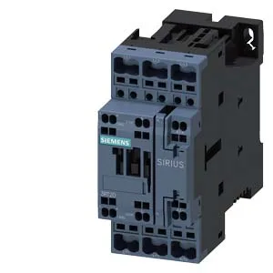
Siemens 3RT2026-2BB40-ZW96 — Contactors

Siemens SIRIUS 3RT2026-2BB40-ZW96 Power Contactor, S0, 24 VD

MPN3RT2026-2BB40-ZW96

Siemens SIRIUS 3RT2026-2BB40-ZW96 power contactor, S0 frame, 24 VDC coil, spring-type terminals, 45 mm width, current lifecycle.

Sourced new & surplus through independent channelsAuthenticity-screened · ESD-safe packingListing updated Aug 2026

Specifications

3RT2026-2BB40-ZW96 — Identification
ParameterValue
Contactor frame sizeS0
3RT2026-2BB40-ZW96 — Ratings & Performance
ParameterValue
Rated operational current, AC-12, max.10 A
Rated operational current, AC-4 @ 400 V15.5 A
Rated value @ 400 V3 A
Rated value @ 500 V2 A
Rated value @ 690 V1 A
Rated value @ 230 V3 hp
Rated value @ 24 V10 A
Rated value @ 60 V2 A
Rated value @ 110 V1 A
Rated value @ 220 V0.3 A
3RT2026-2BB40-ZW96 — Control & Coil
ParameterValue
Control supply voltage typeDC
3RT2026-2BB40-ZW96 — Contacts & Poles
ParameterValue
Main poles3
Main NO contacts3
Auxiliary contact reliability1 faulty switching per 100 million (17 V, 1 mA)
3RT2026-2BB40-ZW96 — Protection & Coordination
ParameterValue
Short-circuit coordination type 1, fusegG: 100 A (690 V, 100 kA), aM: 50 A (690 V, 100 kA), BS88: 100 A (415 V, 80 kA)
Short-circuit coordination type 2, fusegG: 35A (690V, 100kA), aM: 20A (690V, 100kA), BS88: 35A (415V, 80kA)
Aux. switch short-circuit protection, fusegG: 10 A (500 V, 1 kA)
3RT2026-2BB40-ZW96 — Connection & Mounting
ParameterValue
Main circuit connectionspring-loaded terminals
Aux. / control circuit connectionspring-loaded terminals
Conductor cross-section, solid1 ... 10 mm²
Conductor cross-section, solid or stranded2x (0.5 ... 2.5 mm²)
Conductor cross-section, finely stranded w/ ferrule2x (0.5 ... 1.5 mm²)
Mounting methodscrew and snap-on mounting onto 35 mm standard mounting rail according to DIN EN 60715
Side-by-side mountingYes
3RT2026-2BB40-ZW96 — Durability
ParameterValue
Durability (operating cycles, typ.)10 000 000
Durability with aux. switch block (cycles, typ.)10 000 000
3RT2026-2BB40-ZW96 — Environmental
ParameterValue
Operating temperature range-25 ... +60 °C
Storage temperature range-55 ... +80 °C
Installation altitude, max.2 000 m
3RT2026-2BB40-ZW96 — Mechanical
ParameterValue
Width45 mm
Height102 mm
Depth107 mm

Product details

Its 24 V DC coil pulls in at 80% of rated voltage and drops out between 15 and 17.5 ms after coil removal — a tight dropout window that matters for coordinated safety circuits. This contactor mounts via screw or snap-on onto a 35 mm DIN rail per DIN EN 60715, and the mounting position allows ±180° rotation on a vertical surface plus ±22.5° tilt forward and backward. That flexibility simplifies panel layout when orientation is constrained by cable entry or busbar access.

The S0 frame carries main contacts rated for AC-3 switching at up to 750 cycles per hour, with a mechanical life of 10 million operations typical. That cycle limit governs the contactor's suitability for high-duty applications like conveyor indexing or compressor cycling — not just continuous run. For resistive loads (AC-1) the maximum switching rate rises to 1 000 1/h, while heavy inrush (AC-4) drops to 250 1/h. Spring-type terminals on the coil accept solid or stranded wire from 1 to 10 mm², and up to 2x 0.5 to 2.5 mm² per clamp. No screw torque to verify — just strip to 8–10 mm and push in. That saves time during panel build and avoids loose-termination callbacks. The auxiliary contact block is built in, with a configuration of 1 NO + 1 NC (18... 8 in Siemens notation). Its DC breaking capacity is rated at 10 A at 24 V, 2 A at 48/60 V, 1 A at 110 V, 0.9 A at 125 V, and 0.3 A at 220 V — so it handles PLC-level feedback signals but not high-DC loads without derating.

Dimensions are 45 mm wide, 102 mm tall, 107 mm deep — the S0 footprint fits standard 45 mm pitch on DIN rail. These are the minimum air gaps to adjacent metalwork for arc flash containment; a panel builder should not crowd the contactor tighter than that without checking coordination with upstream protection. The arcing time is 10 ms per pole — fast enough to limit let-through energy in a fault scenario, but the upstream breaker's I²t curve should be verified for selectivity.

Frequently asked questions

What are the key ratings for this contactor?

S0 frame size, 24 V DC coil, spring-type terminals. AC-3 switching rate up to 750 1/h, mechanical life 10 million operations typical. Auxiliary contacts rated 10 A at 24 V DC, 2 A at 48/60 V DC. Dimensions 45 x 102 x 107 mm.

What wire sizes does the spring terminal accept?

Solid or stranded wire from 1 to 10 mm², with a maximum of 2x 0.5 to 2.5 mm² per clamp.

What clearance distances are required around this contactor?

Minimum 10 mm upwards, 10 mm forwards, 10 mm downwards, and 6 mm to the side for arc flash containment.

MPN
3RT2026-2BB40-ZW96