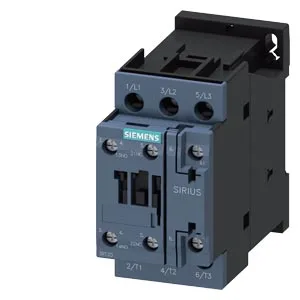
What it is and what it does
The Siemens SIRIUS 3RT2027-1AL20-1AA0 is a Size S0 power contactor with an integrated auxiliary switch, designed for switching motor loads and resistive loads in industrial control panels. It fastens via screw and snap-on mounting onto 35 mm DIN rail per DIN EN 60715, and can be mounted standing on a horizontal surface. The operating temperature range is -25 to +60 °C, with storage from -55 to +80 °C.
Key ratings and what they mean for fit
This contactor is rated for mechanical endurance of 10,000,000 operating cycles, which gives a baseline for maintenance intervals in high-cycle applications like conveyors or packaging lines. The switching frequency varies by duty: up to 1,000 cycles per hour for AC-1 resistive loads, 750 cycles per hour for AC-2 and AC-3 motor starting, and 250 cycles per hour for AC-4 plugging/reversing. The AC-3e rating also caps at 750 cycles per hour. These numbers tell you the contactor is built for moderate-speed cycling, not for high-speed jogging applications.
Auxiliary contact ratings
The built-in auxiliary switch carries rated currents that drop with voltage: 10 A at 24 V, 2 A at 48 V, 2 A at 60 V, 1 A at 110 V, 0.9 A at 125 V, 0.3 A at 220 V, 3 A at 400 V, and 0.6 A at 440 V. These are the contact ratings for the auxiliary circuit — use them to size the control transformer and verify the signal voltage drop across long cable runs. At 400 V the contact is rated for 3 A, which is enough for a typical PLC input or relay coil, but at 440 V it drops to 0.6 A, so check your load if the control voltage is on the high side.
Panel integration and wiring
Dimensions are 85 mm high, 45 mm wide, and 97 mm deep — the 45 mm width is a standard single-module footprint on 35 mm DIN rail, so it occupies one position. Wire capacity for main contacts is 1 to 10 mm² solid or stranded. For the auxiliary contacts, it accepts 2x (0.5 to 1.5 mm²) or 2x (0.75 to 2.5 mm²). The magnet coil uses screw-type terminals. Arcing time is 10 ms, and clearance distances are specified: 10 mm upwards, 10 mm forwards, 10 mm downwards, and 6 mm to the side. These clearances matter when laying out the panel — you need that space for arc flash containment and heat dissipation, especially if the contactor is running near its thermal limits.